Mesh Not Proper!

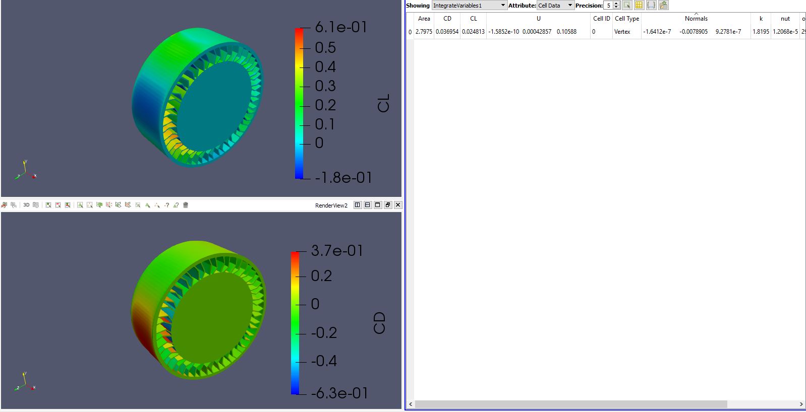
Hello everyone, So i am trying to carry out the external aerodynamic analysis for a Airless tyre with spokes. So basically i want to carry out the simulation for two cases. One when the tyre is stationary with respect to the ground and one where the tyre is rotating. i am applying the boundary conditions as follows
Stationary Case
Inlet - Velocity Inlet - 14m/s
Outlet - Pressure Outlet - 0
Top and side walls - Slip walls
Bottom and Tyre - No slip ( Stationary)
and for rotation case
Inlet - Velocity Inlet - 14m/s
Outlet - Pressure Outlet - 0
Top and side walls - Slip walls
Bottom - Moving wall
Tyre - Rotating wall

But i am not getting satisfactory results for the Rotating case. However the Coeff of Drag and Coeff of Lift in the journal i am referring is 0.774 & 0.513 respectively. So after referring various literature i got to know that a mrf region should be introduced to achieve proper results for such complex geometry cases.
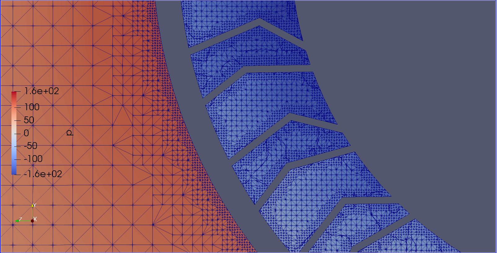
Iā€™ve tried to create the mrf region and have given it a run but i am not sure whether it iss the correct approach or not, so can someone please help me out with it ?

Please be free to ask if you need any more detailss regarding the project! :slight_smile:

Also if @1318980 or @Get_Barried can give some inputs i will be obliged :slight_smile:

Hi @simscale8,

Iā€™ve post-processed your results in ParaView. As you can see in the screenshot below for CL and CD. Your results are very off by almost 95%. This is probably due to a number of reasons.

The first thing I must clarify is that the calculation of CL and CD is based off the lift and drag equation. While the variable of density is most certainly correct, the speed and effective area might be incorrect. I have based off the speed as your inlet velocity of 14 m/s to obtain this CL CD data that you see now. It may be incorrect on the other two variables so Iā€™ve gone ahead and explain what I used.

However, if we think about the rotating zone, your inlet velocity may not represent the correct velocity, as such Iā€™ve went ahead and measured the geometry to obtain the velocity which is slightly less than 14 m/s, so assuming this is correct, the results donā€™t deviate as much so no worries there.

Effective area however might be an issue. Iā€™ve merely extracted the surface area from Paraview as you can see in the figure under ā€œareaā€ and from what I can see it may not be accurate. So do let me know what the surface area is of the wheel.

On to the other possible sources of error.

Referring to the figure below. Your inflation layers for achieving your Y+ is not present at all. This is likely due to the mesher erasing your Y+ due to the quality control. Refer to this post here to possibly fix the issue. Also ensure that your ā€œMinimum overall layer thicknessā€ is significantly less than the actual overall layer thickness. It will just erase the layers if the inflation does not exceed this limit.

Next, same issue with your bounding box inflation layers, they are not showing up. This one you can refer directly to your project and observe that at the bounding box, there are no layers at Y min. The likely fix is similar to that of the previous paragraph.

Also for you boundary condition ā€œBottom-MWā€ is it supposed to be assigned to the inlet face as well? I donā€™t think so, so do remove that unless Iā€™m mistaken.

You will lastly need to ensure convergence is met. Your current residual levels are quite high and unless somehow this is alright, you want to get them below 1E-4 at least. This means adjusting the numerics for your relaxation values for p or U by decreasing them. Do ensure the end time is longer if you do this as it takes longer to converge. Ensure that your mesh and boundary conditions are alright first.

Hope this helps.

Cheers.

Regards,
Barry

2 Likes