Can anybody help me understand and solve the problem for my mesh?
I am not able to mesh my geometry (Formula 1 2017 CAD)
I keep getting an error when trying to create the mesh.
Project found:
Thanks
Can anybody help me understand and solve the problem for my mesh?
I am not able to mesh my geometry (Formula 1 2017 CAD)
I keep getting an error when trying to create the mesh.
Project found:
Thanks
Hi @alex_07_guer:
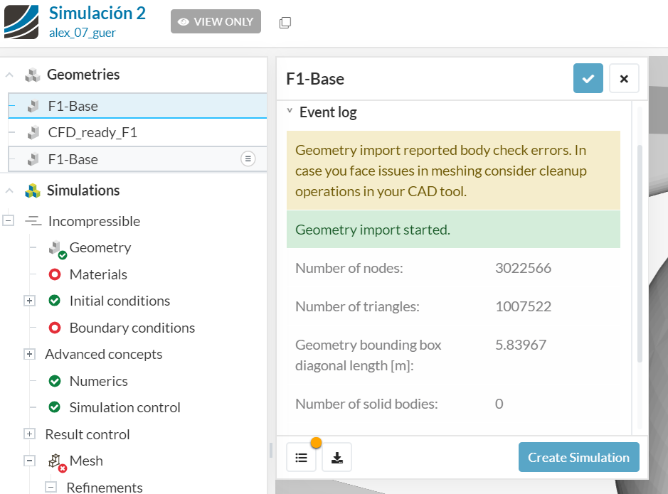
You had warnings already when importing your STL file:
You have nice model, but it should be at least 1 solid.
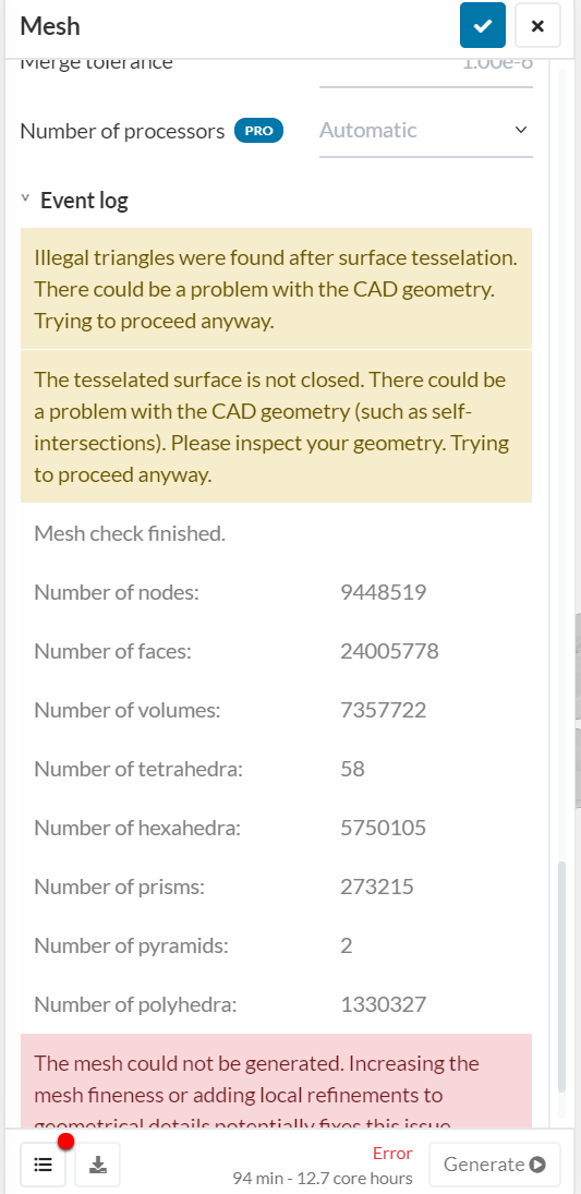
Next warning (error message) comes from mesh process, which should not even be started without having a solid body, but it tried hard:
Your model needs the fix in that respect. I also consider that you should start with simpler model: current model has a lot of details and you will spend a lot of core-hours just to figure out how to do a correct mesh (you use parametric mesh, so many things can be tuned). For instance, setting the BL on car body only is not a good idea…
Cheers,
Retsam
Hi,
I have just created another project with an “official” geometry which is supposed to be cleaner than the one I used before. https://www.simscale.com/workbench/?pid=5650292781324893026
Would you say it is propperly meshed?
I want to run a simulation on it.
Thanks.
Well, you do not need new project for every new simulation. Just add geometry to existing one and create new simulation.
Your current mesh is > 10 MCells and > 18 MNodes. Meshing took > 200 core-hours. So there is some progress. But in reality, you should abandon the idea of any CFD simulation with that mesh. It will screw even a 3D printing.
I suggest you copy first some public projects (with simple car models) and run tutorial about meshing. This is Ba ba of somebody wanting to learn something about CFD. We can help you, but for the moment I feel helpless and you did not follow my first advice: make it small and simple. Learn from it and then, when in trouble, be back.
Otherwise you will be left with no core-hours in few weeks or perhaps even at the end of this week.
Cheers,
Retsam
Thanks for the advice.
I have already performed several tutorials and “easy cases” but I still want to simulate the F1 car. How could I fix the geometry in order to generate at least one solid?
Thanks
@aguerrero: you should not use STL format first. It is used for 3D printing and I also used in the past for very simple shapes, but in that case you need something else.
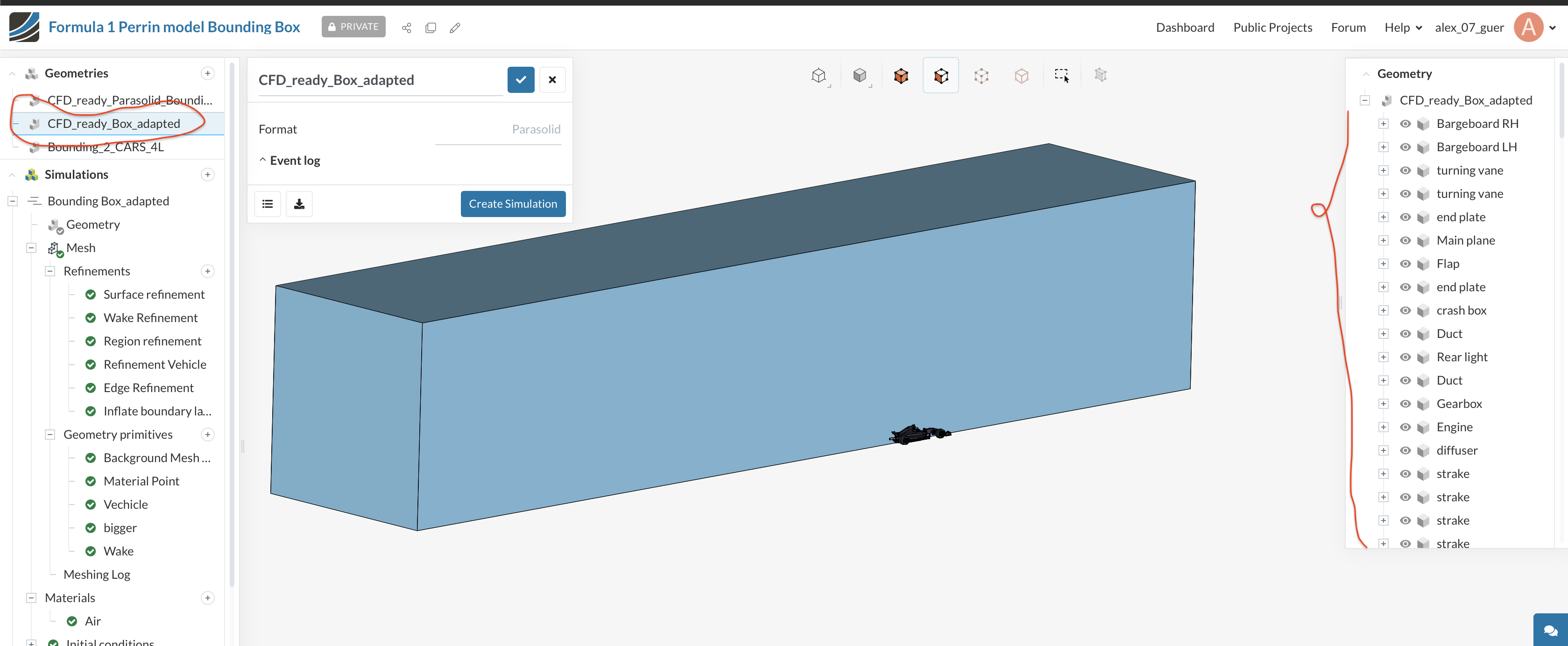
If you know OnShape, direct import from OnShape uses ‘parasolid’ format. In that case you will have quite a few ‘solids’, for instance every wheel will be a separate one.
But still, in my opinion, you should exercise on your own, very simple ‘soap box car’ model of car, in order to understand how to correctly define meshing parameters, setup simulation, measure drag coefficients, rotate wheels, move road, etc. Your current model will need months of your time: you need to progress making simple things obvious first.
Cheers,
Retsam
Thanks for the advice. I am working now with a Parasolid geometry from Onshape.
What kind of mesher algorithm would you recommend for such a CFD analysis? Everybody suggests Standard but I am not so sure.
Cheers.
Well, so far so good. For th moment I suggest HEX (external CFD). Start with automatic, very harsh, it should by as quick as possible. You will refine few times. Later on you may need HEX parametric…
Cheers,
Retsam
Hi,
After several attempts, I finally managed to simulate properly the F1 model with its bounding box.
Link here: https://www.simscale.com/workbench/?pid=5650292781324893026&mi=geometry%3A61&mt=GEOMETRY
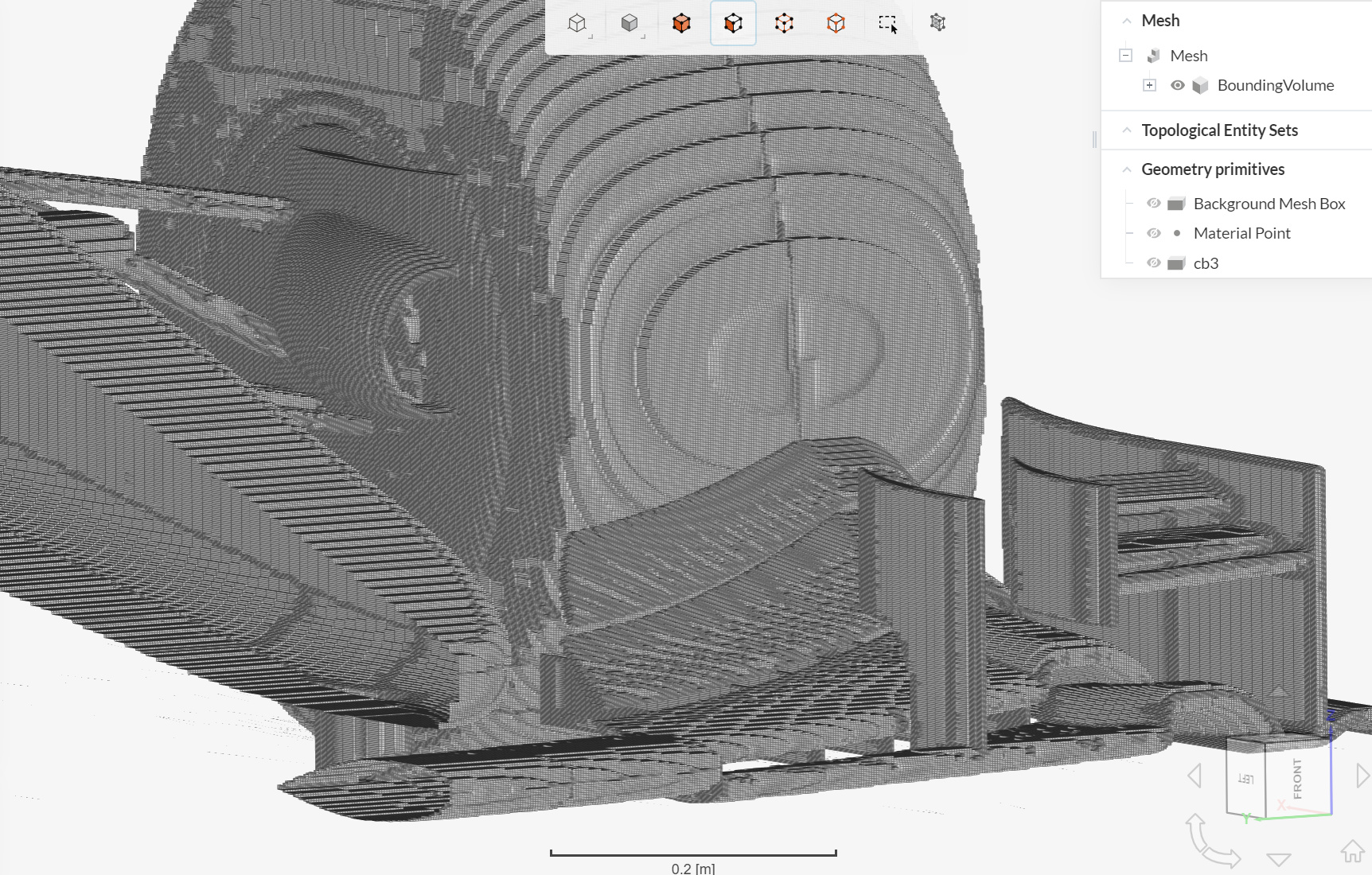
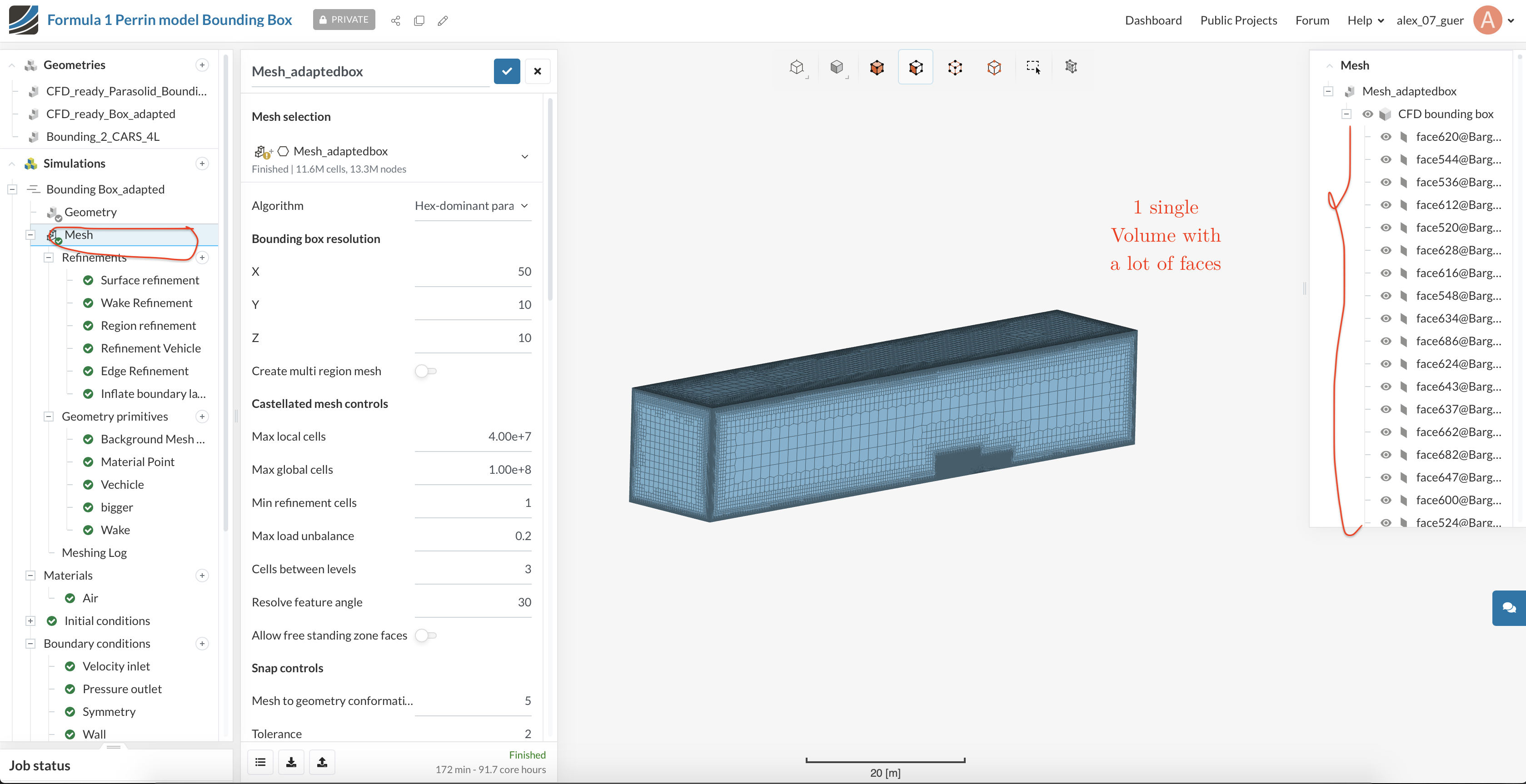
My question is: Why after the meshing procedure all my solid parts disappear and I only get a single solid with thousands of faces inside it? If you look at the geometry when you import it, you can see several solids with their faces inside, but after meshing all this information disappears. The results are still there, because I have post-processed it with paraview and I get beautiful results, but it would be much more comfortable to keep the solids that are initially detailed so I could for example only show the front wing in the post process and not the whole car.
I attach a couple of images to help understand what I mean.
Cheers.
Hi @alex_07_guer: Simulation is about flow of air, in your case. Mesh for CFD represents that air: all solids you had were used to get the form of the air in your simulation domain.
Imagine you had a solid sphere in your BMB. For simulation purpose you need the volume of the air around the sphere. Hence sphere itself is removed, as not necessary for CFD simulation. However mesh preserves the shape of the sphere, as ‘negative’ of it.
Cheers,
Retsam
Hi
So, there is no way to keep the solid volumes?
It is very annoying for the post process just to have thousands of faces. Do you know any way of merging those faces into just one?
Cheers,
I suggest you use, once mesh is generated, ‘Topological Entity Sets’:
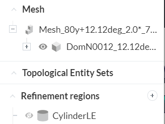
It is still manual, but once those entities defined, you can easier use them while defining pointer to Forces and Coefficients, etc.
Okay, but will I be able to see these group of entitites for example in the Paraview post processor? Because all I see now is almost 5000 faces and it is very hard to know what is what.
Cheers
I do not know, as I don’t use ParaView. I suggest you try a tiny geometry yourself and import results in ParaView. Please publish your results on that forum: It can be useful to others as well.