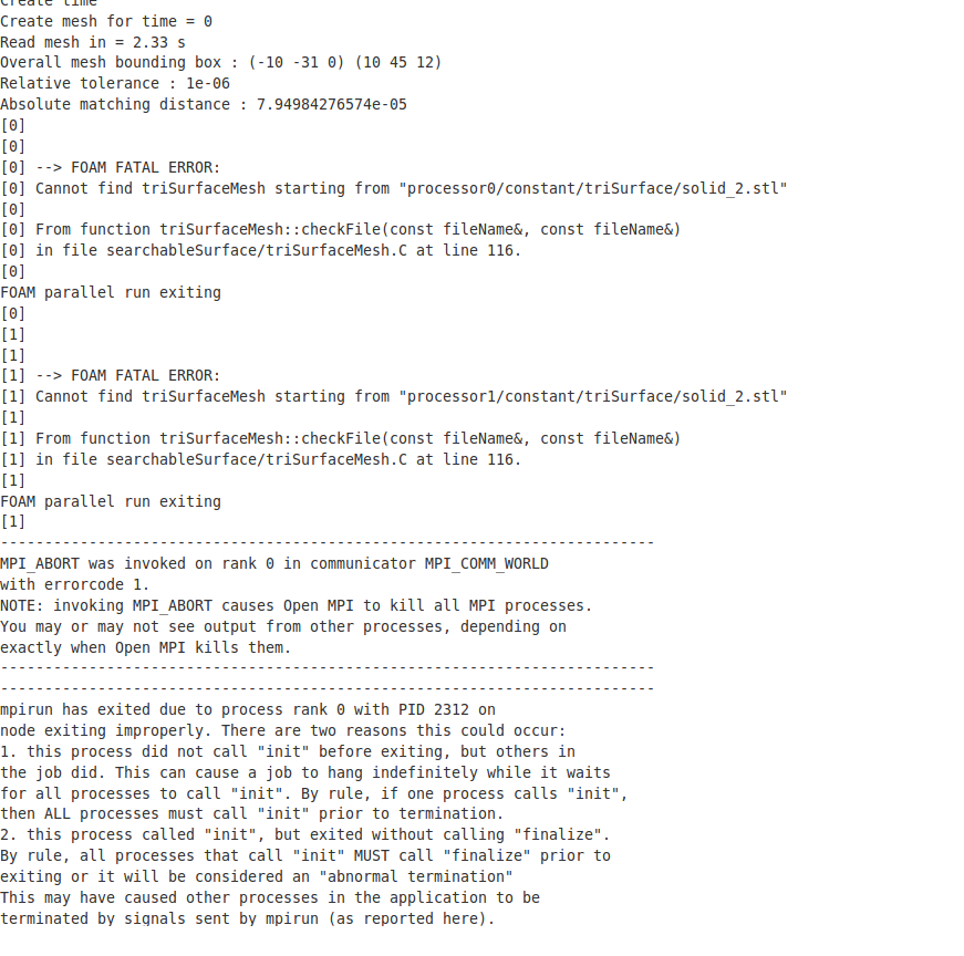
I am a new user to Simscale, Please help me solve this error. I don’t understand the error. I have created the model using CATIA V5 and converted it into STEP file. I am trying to employ ‘Automatic Snappy Hex Mesh for External Flow’.
Hi @ch3316
Thank you for reaching out to us.
I have taken a look at your project and found no issues with your STEP CAD import. So the mesh Error basically points to some internal failure during the meshing process.
Our product team ( @jprobst ) will take a look at it and we will get back to you as soon as possible.
Best,
Ali
1 Like
Hi @ch3316
thanks for posting the error! We are looking into this and will report back once resolved.
All the best,
Johannes
Hi,
Thanks for looking into my problem, but I have solved the mesh problem but having problems with simulation. I changed CAD file file to stl format and cleaned the surfaces using ‘feature angle surface’ geometrical operation. Mesh was generated and it is fine. I don’t know how change in file format solved my error.
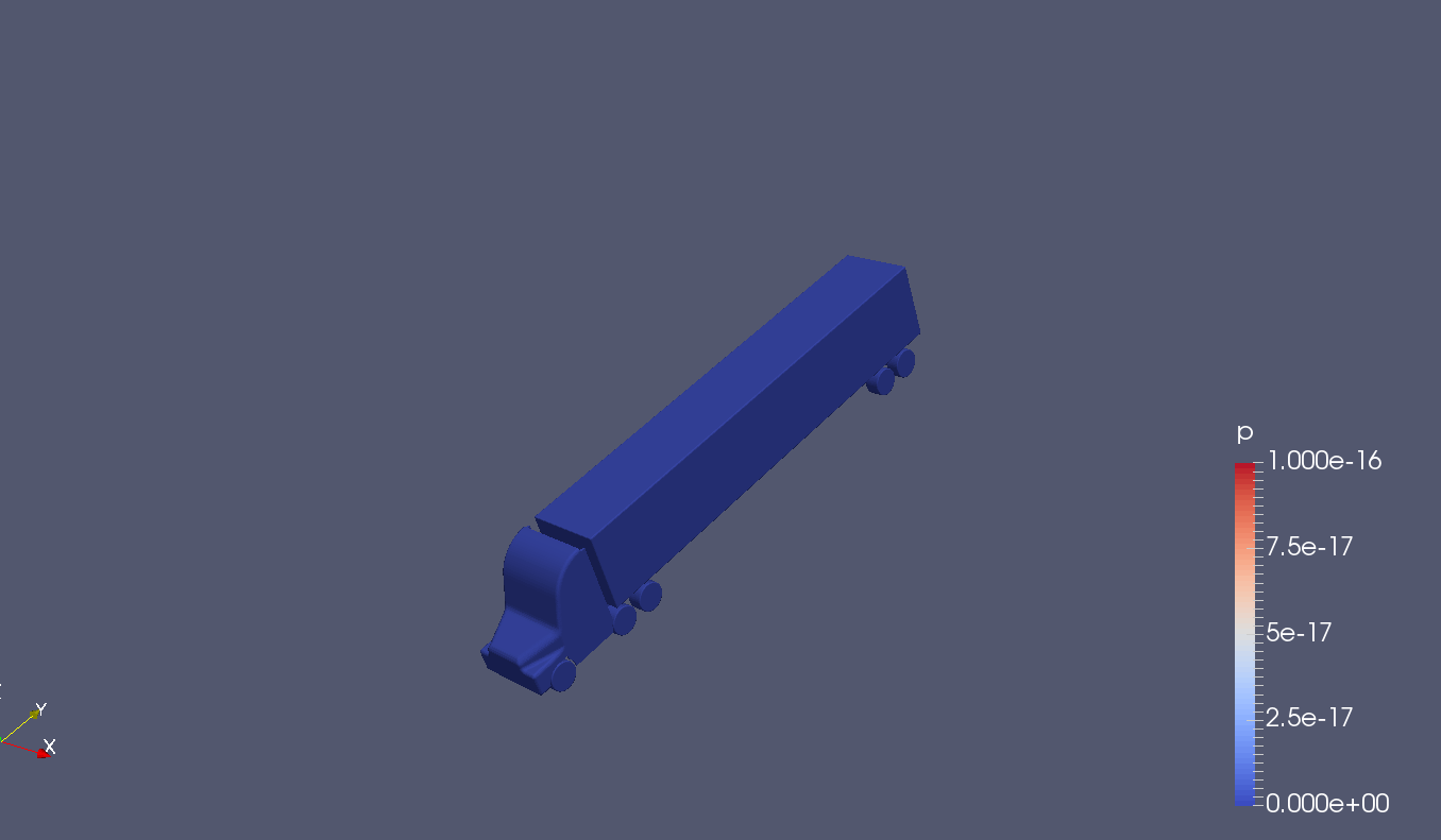
However, I was running the simulation at a 60mph inlet velocity. I have set all BC and after running simulation, there is no flow development in the domain. Even my solution didn’t converge, atleast there has to some flow development, right? Pressure all over the Wind Tunnel is zero. Am I making any silly mistake in physical setup or what is happening, I am unable to comprehend. I have compared my physical setup with example (F1 car & Futuristic Car Aero simulation) files available on simscale. Please help me figure out the error. thanks
Hi @ch3316,
could you hint me to your project such that I can have a look at the setup? Is it this one: SimScale ?
Thanks!
David
Yeah, That is the model. Thanks.
Hi @ch3316,
so I had a quick look at the results:
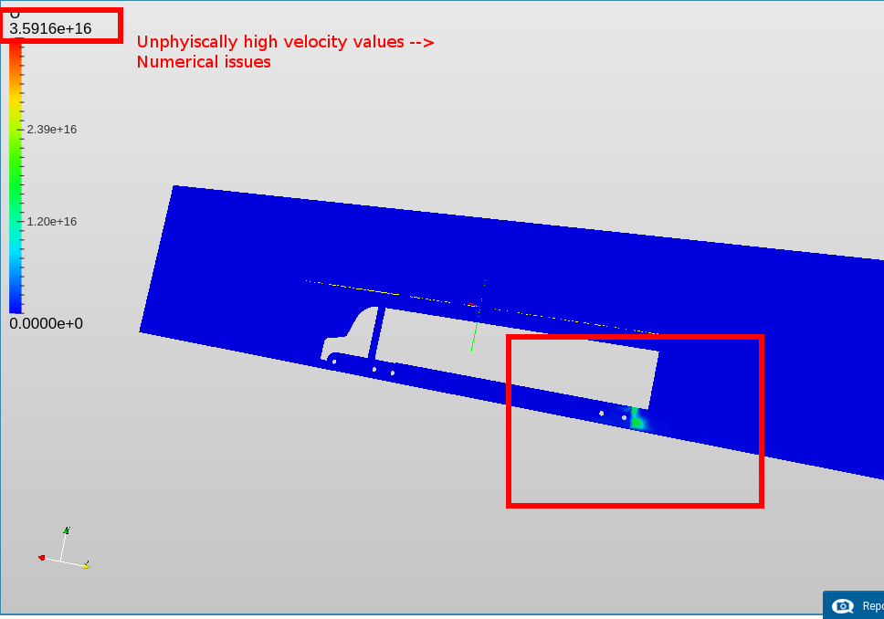
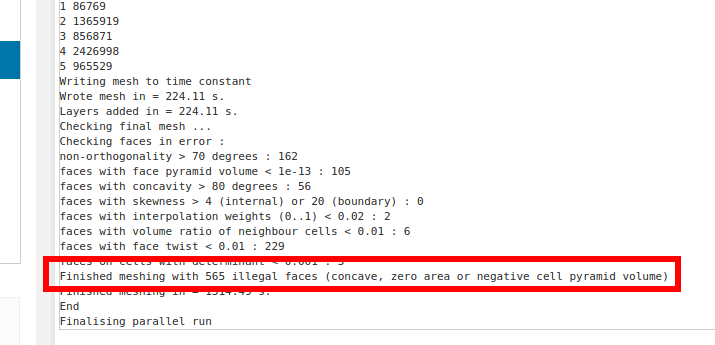
The velocity says peak at 3.6e16 which is clearly unphysical since you ran a sim with 60mph. So there either is an issue with the mesh or a numerical issue or both. Then I looked at the mesh you used. The meshing log indicates that this mesh contains illegal faces which explains the unphysical results:
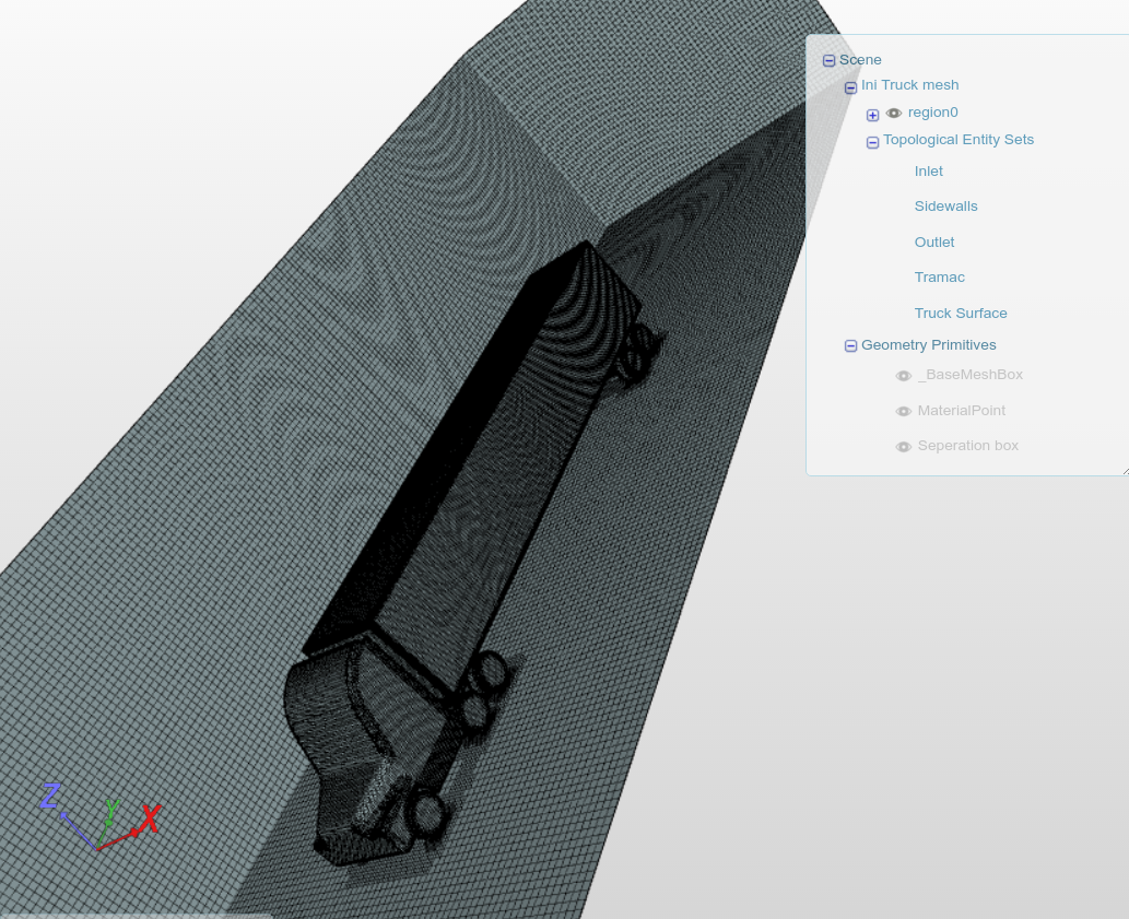
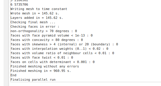
But I saw that you already generated another mesh, right. That seems better:
So I guess if you re-run the simulation using the new mesh, everything should be fine. The simulation setup in general looks absolutely correct to me.
Hope that helps.
David
1 Like
Hi,
Thanks for your help David. I didn’t think about checking the mesh.
I like to know how to calculate initial K and omega values for the simulation. I have theoretical knowledge of CFD theories but I like to know how to do a good estimate of initial k and omega. Thanks
Hi,
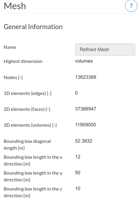
With the new mesh I have created, I have started a new simulation. However it stopped running after very few iteration. My mesh details are shown in the following figure.
The error shown for the simulation:
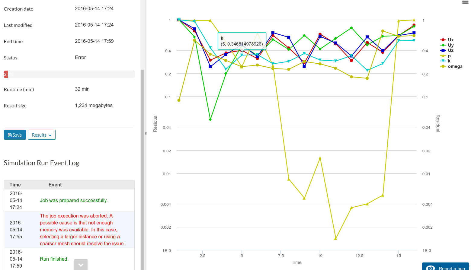
Is this due to mesh having high number of nodes and cells. I have tried reducing number of instance (and deleted some files and previous runs) from my profile but same error appeared again. I am using 32 cores and is there any possible solution other than reducing cell size, if so what is the optimum/highest number on Simscale because every time I have simulation error, I waste my core hours. Thanks for your time.
Hi @ch3316,
your mesh has 12 million cells, so that should be a piece of cake for a 32 core machine. I copied your project and will give it a try myself. Will get back to you once I know what’s the issue.
Best,
David
so I tweaked a bit the numerics + simulation control settings and started a run myself. Will post it here soon - but when looking closer at your project, you already have working simulation runs, right? The 2nd and 3rd of your half model look good, don’t they?
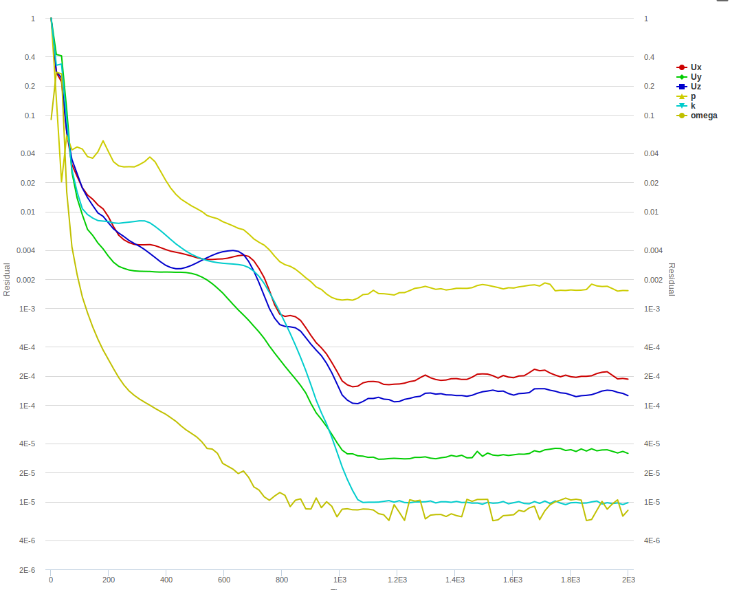
Having the pressure residual “only” going down by 3 orders of magnitude but not more is something I oftentimes see in steady-state external aero analysis. Could be a mesh/numerics thing but it could simply also be transient flow effects, that can not be captured by the steady-state solver, what do you think?
Best,
David
1 Like
looking at the results of your other runs, there’s one thing I’d change in your simulation setup:
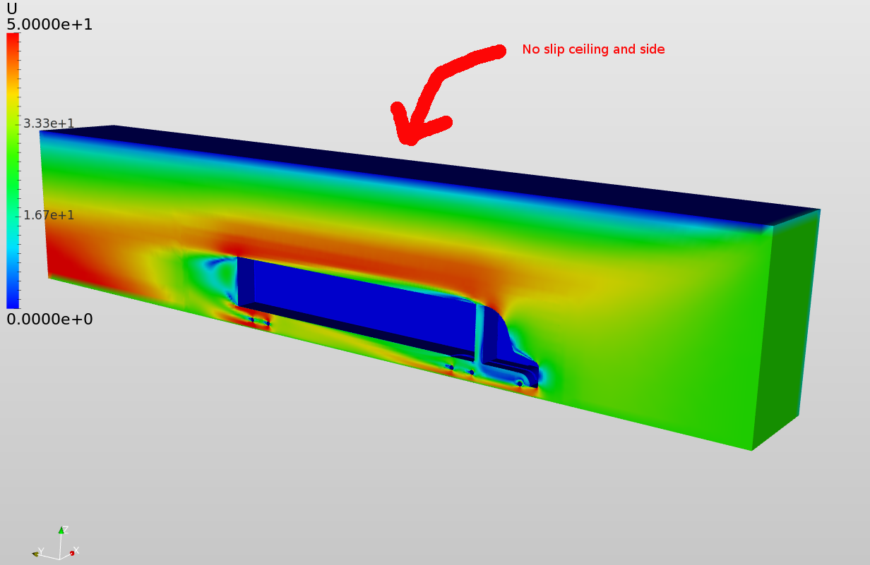
You treated the ceiling and side walls as “No slip”. Depending on what you want to simulate (do you want to “replicate” a wind tunnel situation or an actual street/outside situation) I’d make that slip walls. Your floor is moving, so I guess you want to simulate “the outside” situation, right? So slip would be the better choice.
I tweaked some Numerical settings:
- Orthogonal correctors = true
- Higher residual convergence criteria
- Geometric/Algebraic Multigrid solver for pressure + some settings changes in there
as well as some Simulation Control settings:
- Initialized with potential flow solution = true
but overall I think your setup is correct. The domain might be a bit small to sides and the top of the truck, especially to the sides I’d expect an interaction of the solution fields with the side walls, so to get better result I’d make this larger.
Find my project over here: SimScale
I ran both a run with no-slip and slip ambient walls. Simulations are currently running - let’s see how they go.
Best,
David
2 Likes
Hi Dheiny,
Thanks for your support. I thought reducing the number of cells cells will finish the simulation without memory error. So, I did the half model. But I had the same problem again. When I changed the pressure solver from GMAG to PCG, simulation ran without any errors. I was worried about the number of cells, so I walls are very close the vehicle. I will do another run with bigger mesh box and different settings. How can I create convergence plot for Drag along with other variables in convergence graph.
Hi @ch3316,
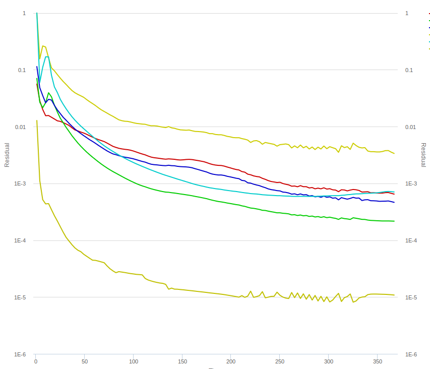
my sims ran 350 iterations now and so far, it looks okay (I’m running with GAMG). Strange that you had problems with GAMG - generally my experience is using this multigrid solver accelerates convergence and never adds problems / instability.
For drag, add a result control item (see “Forces and moments”) for the truck itself. It will compute the force acting on the truck in all directions.
1 Like
Hi,
I want to calculate drag for my model. Can I do this using Post-processor in Simscale? I have tried using Paraview but couldn’t find an option to calculate drag (similar to ANSYS). I have tried using surface normals. But this method doesn’t calculate area of the element on the surface. My method is to calculate force in Y-direction as (normal_Y*(101325+p)*A), where p is pressure data and A is area of the surface element on the truck. And adding all the cells in the result would give me drag, right? I am unable to find options to estimate A of each surface cells. Thanks for your time.
you can calculate visualize drag after the simulation using Paraview. This little blog post provides guidance on how to do it: Aerodynamics Post-Processing with SimScale and ParaView. To compute the drag coefficient of the whole body, the result control items within SimScale (SimScale Documentation | Online Simulation Software | SimScale) would give you results immediately as opposed to doing any post-processing afterwards. But there is also a way to do it “retrospectively” with Paraview, I’ll try to find a ‘how-to’ on it.
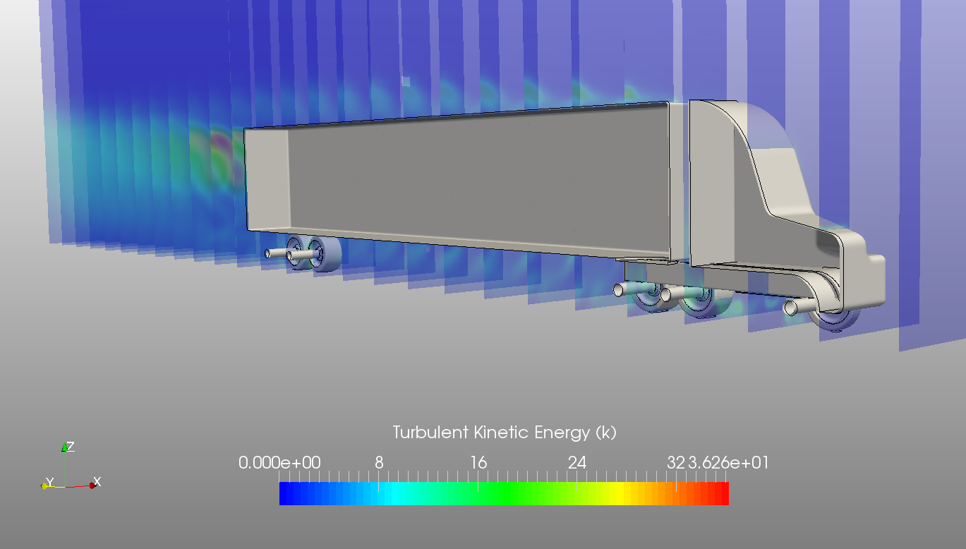
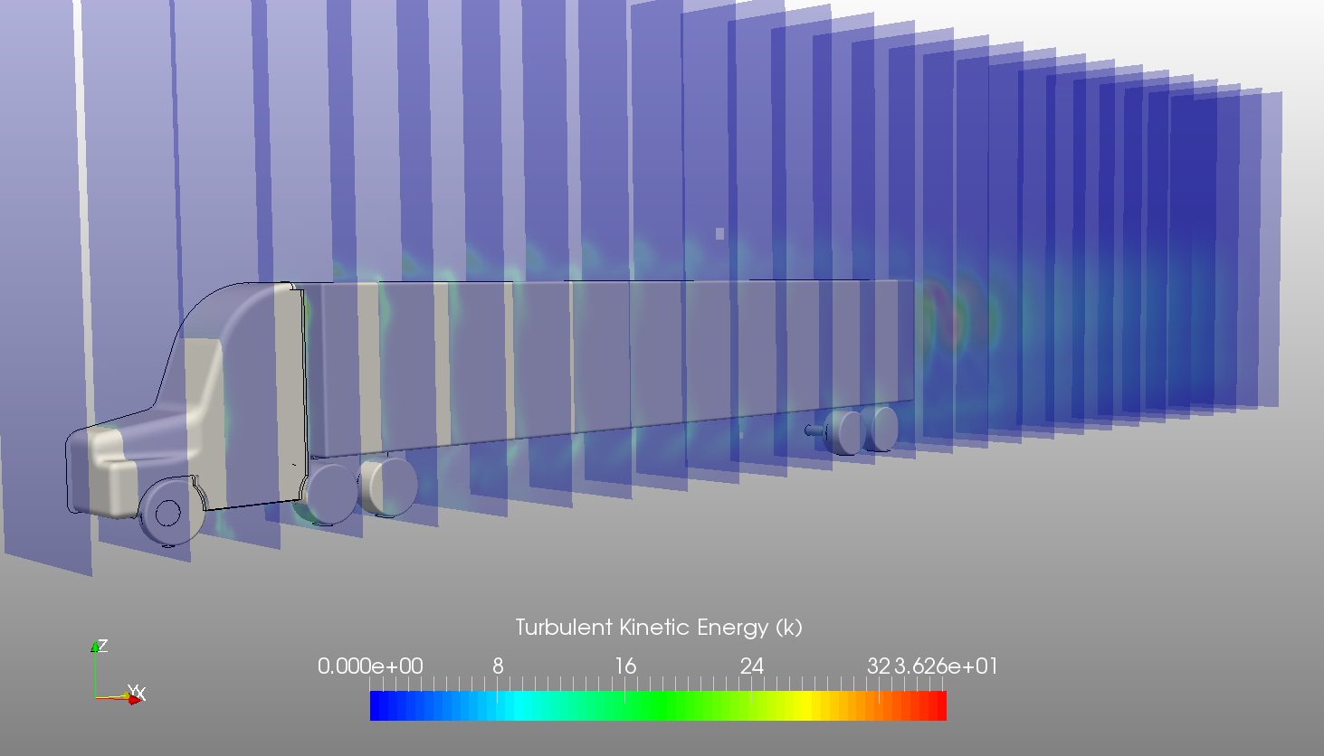
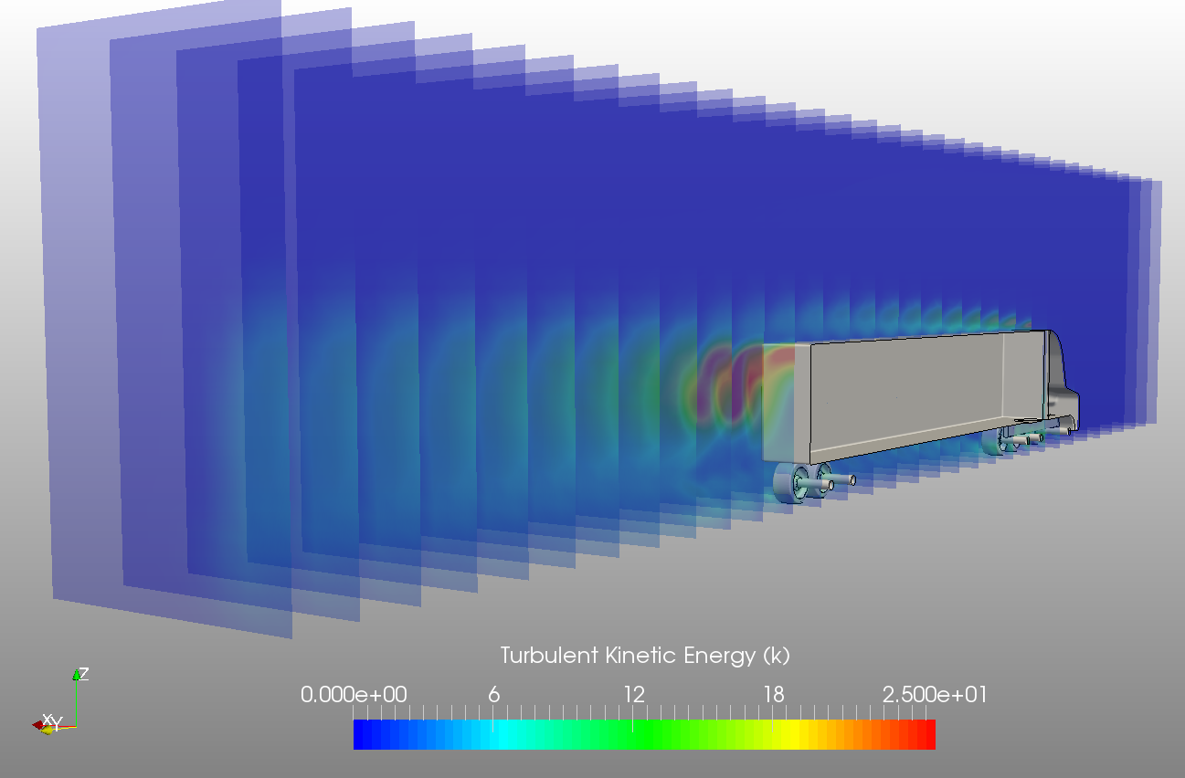
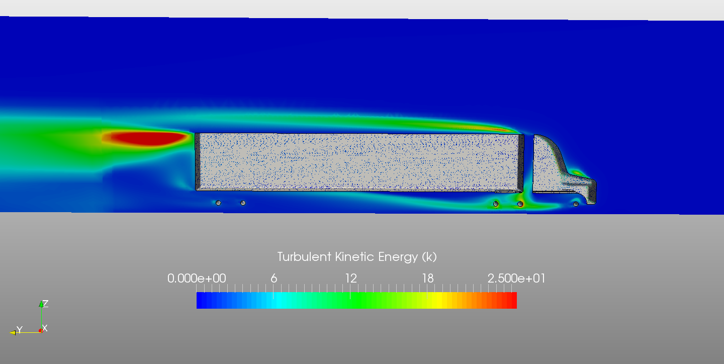
By the way: My sims finished in the meantime as well. Pressure residual does not go below 3 orders of magnitude either - so might either be mesh or transient effects. Did a quick visual post-proc locally:
Staggered slices of turbulent kinetic energy:
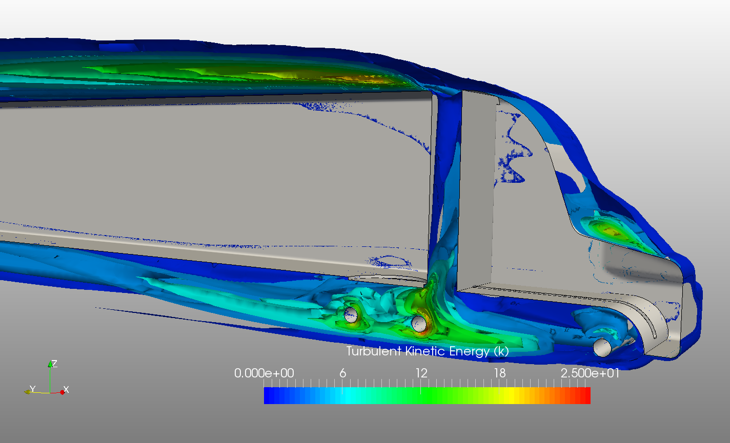
Isosurface plot of the turbulent kinetic energy k:
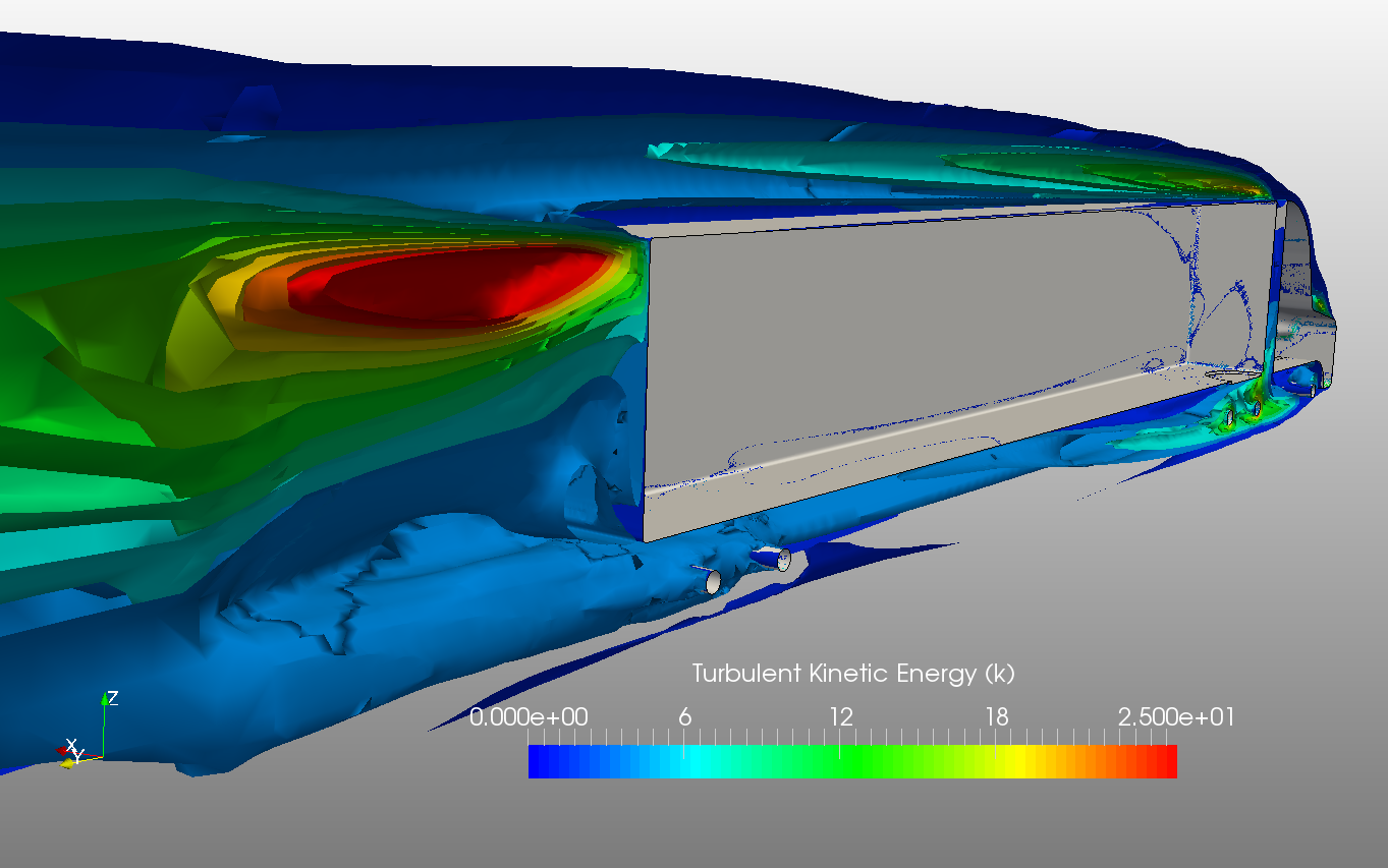
Clip plot of the turbulent kinetic energy k:
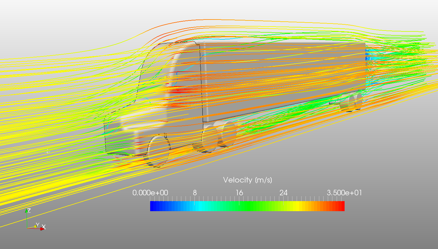
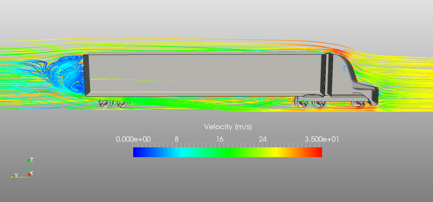
Streamline visualization of the velocity field (m/s):
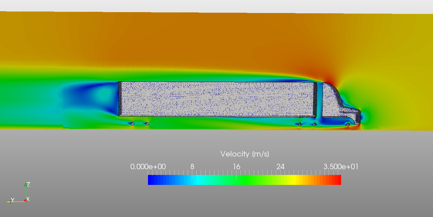
Clip plot of the velocity field:
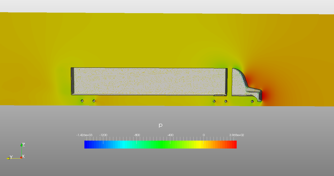
Clip plot of pressure:
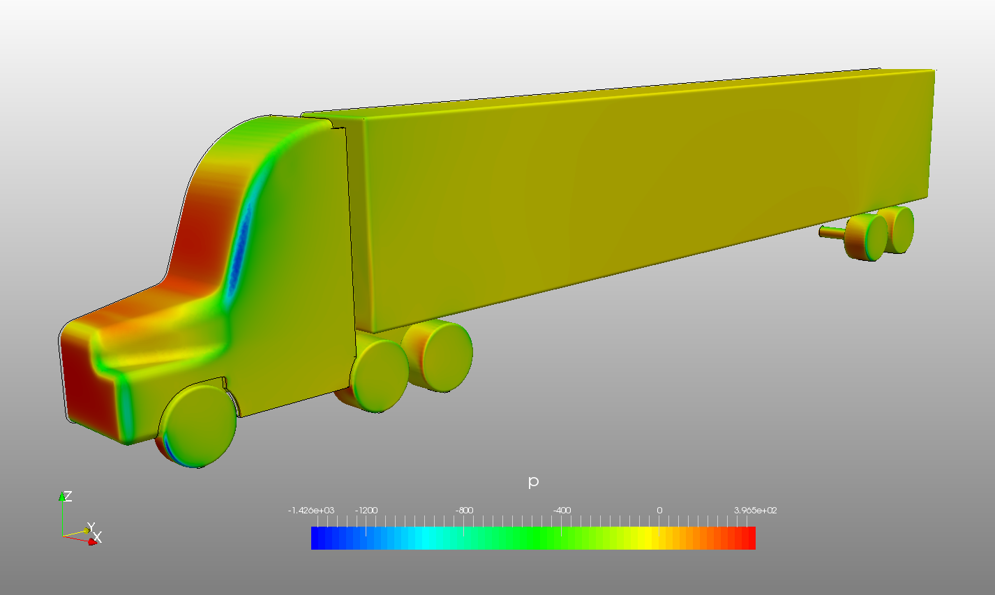
Pressure surface plot
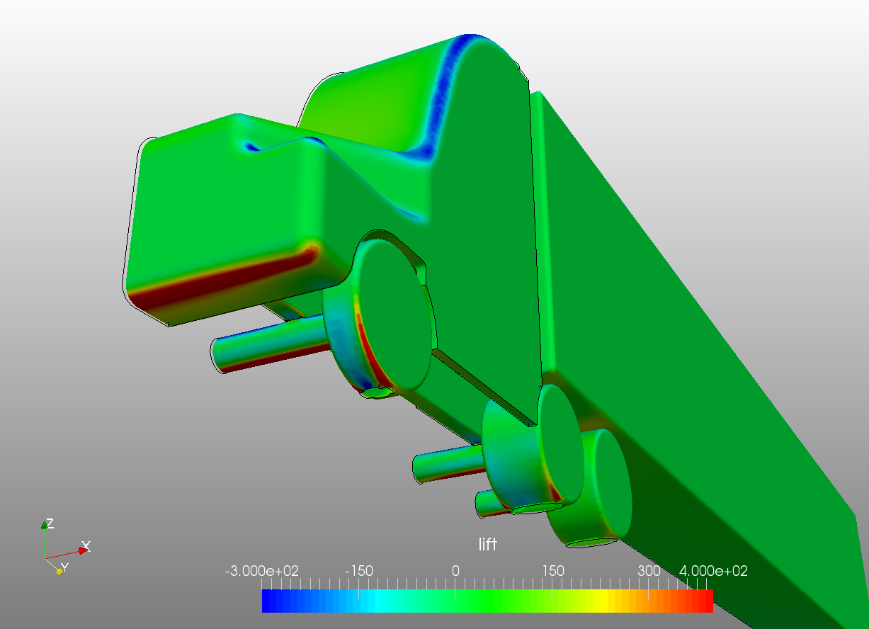
Lift surface plot:
5 Likes