Cell layer inflation and yPlus

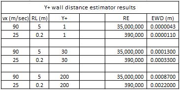
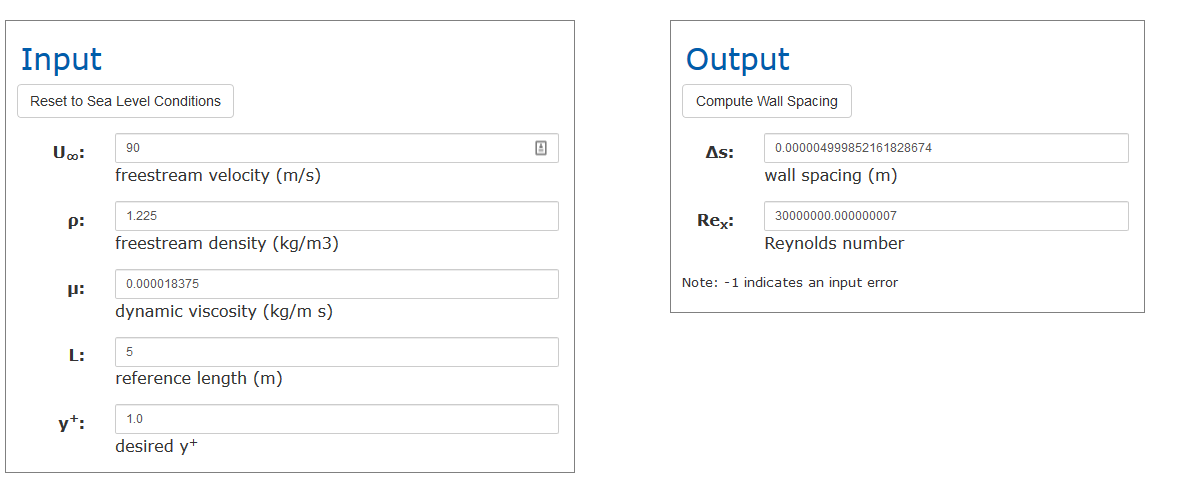
I researched Layer inflation by reading the forum guides but it did not seem that I had the same parameters available to me and my geometry is a complete aircraft where I could not figure out what reference length to use for the y+ online calculator.

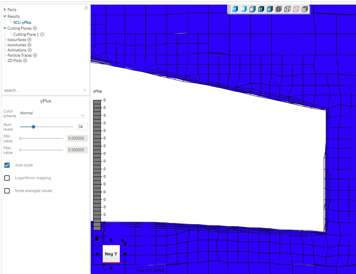
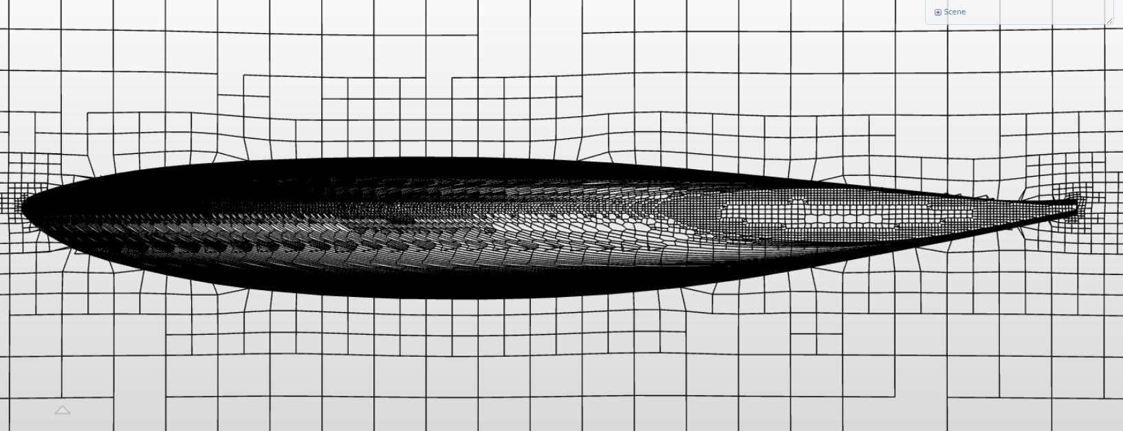
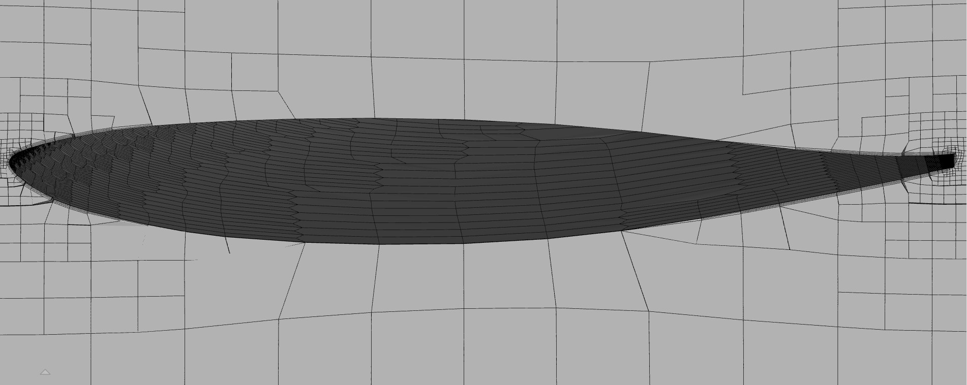
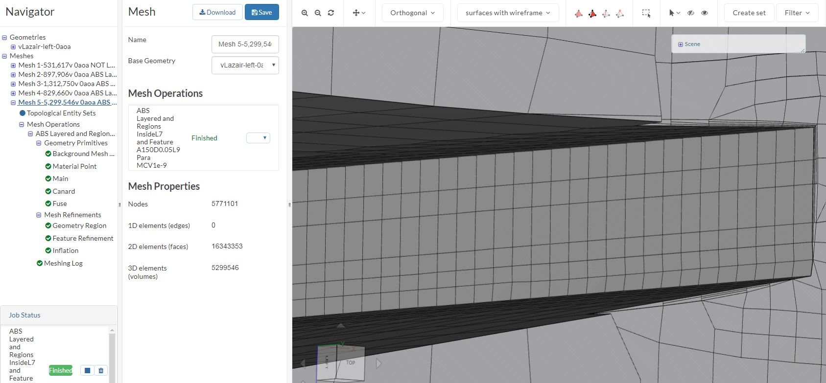
Anyway I decided just to mesh with the default settings that popped up and I got what I think is a result but the boundary layer looks pretty thin in some places, below is the mesh at the trailing edge of the main wing whose trailing edge thickness is about 12mm thick. I am showing a cutting plane whose scalar is yPlus but the max and min value on auto scaling are both 0 (EDIT: Correct me if I am wrong but from what I have learned since I started this topic, it turns out that this is because yPlus values seem to only have a value near a geometry surface so I should not have expected anything but zero elsewhere when I tried to map it to the internal mesh… Live and learn… :wink:)

  1. Do those 0 max/min values mean I did not succeed in getting a boundary layer in the mesh?
  2. To me, It does visually look like there is a boundary layer in the mesh but if the trailing edge is 12mm, then the BL thickness looks like it is less than 1mm thick. Will this give me good results as far as how the boundary layer affects the aerodynamic forces and moments I want to extract from the results?

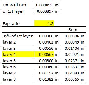
Here are the default parameters I used, not sure why the assignment shows 0s but it did says 13 faces when I created the mesh:

InflateParameters

Hi @DaleKramer!

Let me tag @Get_Barried & @vgon_alves here who might help you out with that one :+1:

Cheers!

Jousef

Hi @DaleKramer,

Do you have a link to the project?

There has been a quirk within ParaView/the post-processor where the yplus filter sometimes does not accurately display the corresponding value. Checking the actual layers you did for the figure you posted is the more reliable way to deduce if the correct layers have been generated.

You will need to follow the yplus calculator to determine the needed layer size and correspondingly, the turbulence model used along with what you are trying to investigate. For your case, I assume you’re using the K-omega SST turbulence model with often dictates a yplus of less than 1. However, if you use a wall function your yplus must now be within 30 to 200 which will reduce the computational cost of your mesh. If you considered what I just carefully for your case then you should get adequately accurate results from the layers you generated.

However, this does not mean your overall results will be sufficiently accurate. Additional factors like mesh quality for the other parts of the mesh, your boundary conditions and numerical schemes will play a significant factor in you eventual result accuracy.

Cheers.

Regards,
Barry

1 Like

Barry, thanks for the information. I just pm’d you about a link.

Specifically, I do not understand how to set the reference length for using the y+ calculator. My aircraft has airfoils of chords between 8 and 34 inches and that does not take into account the fact that the fuselage is 180 inches long. The aircraft will have be analysed for speed range of 60 to 200 mph.

  1. How could a single set of input parameters to the calculator account for those ranges?

So I made a chart of some reference lengths and speeds and desired Y+ from the online Y+ calculator:
EWDrange
The EWD (Estimated wall Distance) ranges from 0.0043 mm up to 2.2 mm.
I am using K-omega SST turbulence model and I am using no-slip walls on the aircraft geometry.

  1. Have I provided enough info to answer this… What values would I use for the 4 ‘Inflate Boundary Layer’ parameters that are available to me now in the current workbench as shown above?

I do understand that many other things also determine the accuracy of my results but here I am only concerned about boundary layer influences.

EDIT I just figured out that the reason my ‘Inflate Boundary Layer’ Parameters are different from what I have seen on forum topics about Y+ is that I am creating the mesh using Hex Dominant algorithm (which I REALLY want to continue to use) and that is one reason I am so confused :frowning:

Dale

Hi @DaleKramer,

Apologies for the delayed reply, haven’t had full access to a PC these past few days and maybe for the rest of the week as well so my replies may be a little slow.

Ideally you would consider all the different reference lengths and have different layer inflation sizes for each one of them. This is however, obviously, very tedious and you may not have the time to do that even if it gives you the most accurate result. So a good place to start would probably be taking the smallest reference length and applying that layer inflation parameter to the entire body to make your life easier. Computationally it would be quite expensive and not very optimized but it certainly would save you much time and effort. You can start with that and maybe re-adjust some parameters for the inflation layers to better fit other reference lengths in order to better optimize the mesh.

Using the y+ calculator lets pick say the first set of values in the table.

From the calculator, you can see that your first inflation layer has to be 4.999 x 10^-6 m for a y+ of 1. This post here should help with implementation of the layers.

Unfortunately, the Hex-Dominant automatic meshing algorithms do not allow sufficient control of the mesh. My recommended changes can only be implemented with the Hex-Dominant parametric option. It does seem complicated but after looking through the options for meshing you’ll find that you’ll mostly have to deal with the refinements mainly. The earlier post i stated will surely help in the most complicated area of implementing the inflation layers to the desired y+ value.

Hope this helps.

Cheers.

Regards,
Barry

1 Like

Wow, I was afraid of that (about needing to use the parametric option).

I have played with that algorithm but have found that the default values of the options do not get me anywhere near the mesh of an automatic algorithm on simple geometries. In fact, I do not think I have ever been able to get an error free mesh of my whole aircraft geometry and the list of parameters is so overwhelming and the difficulties in error code analysis make it so that I don’t even know where to begin.

  1. Has anyone ever though of having an option that presents the ‘parametric’ algorithm parameter values that were effectively the values that the ‘automatic’ algorithm came up with for its meshing output?

I hope you can understand that question. Basically I want the parametric default options ‘filled’ in with what the ‘automatic’ algorithm came up with as a place to start for further refinement of the mesh… I think that question deserves its own topic, what do you think?

Before I begin the quest to successfully use the parametric option on the whole aircraft geometry, I will just experiment on a main wing only as I have in the XLFR5 vs CFD topic.

I will report back here after that and hope that the results there will let me continue here…

2 Likes

Hi @DaleKramer,

I’m unsure about what exactly the automatic meshers do different from the parametric ones and correspondingly will not be able to recommend the set of parameters needed to allow the parametric mesher to act more like the automatic one.

However, the difference between the algorithms is primarily dictated by the quality of the geometry. Simply speaking, the more simple and “clean” your geometry is, the difference between both algorithms will be minimal. For complicated or low quality geometries, the automatic algorithm will (i guess) auto correct the parameters to best keep the mesh as high quality as possible. The parametric one does have quality controls if you look into but they are able to be adjusted, hence by default the parametric option will give a lesser quality mesh should you not adjust the parameters as needed.

So my solution would be to ensure that your geometry is as simple and clean as possible. Make sure there they all well defined enclosed surfaces, good CAD practices are implemented through drafting of all components and features, avoid geometrical anomalies like zero point edges or strange sharp outcroppings and so on. From there, meshing would be less of a hassle and minimal or even zero illegal cells can be obtained with little need to adjust any of the underlying meshing parameters.

I could help in this regard which I will detail more in the PM but otherwise this is the likely proper step to head towards in order to produce a workable/accurate mesh.

Cheers.

Regards,
Barry

2 Likes

Hi Barry, @Get_Barried

So I have learned a lot with the help of Darren @1318980 since I was last here but now I am working on this whole plane project again. I have refined the CAD model a little as you suggested and I have taken the plunge and started using Hex Dominant Parametric methods with some success, vs Hex Dominant Auto.

I am still having an issue inflating the layers.

For some reason this elliptical leading edge sweep seems to be much harder that the linear multi-taper leading edge sweep of my simpler public wing project , which I think I got a decent layered mesh of, that only has a couple deflation’s. I can not get any where near that success using the same techniques.

Any chance you can have a look at the project and suggest a different approach?

I looked at all of these at y=-60 (~1/2 span) on the rear wing to get a 1st off view of layering quality

  • Mesh 1 : NOT layered test of basic geometry meshing
    Quality : Good

  • Mesh 2 : ABS (not relative) layered mesh with 3 layer, 0.3m reference length and a sum of layers thickness of 0.105 inches
    Quality : Decent, here is clip and yPlus map. The problem with this yPlus map is obviously on the Fuselage, that is why I am trying to layer with 1/2 fuselage length (2.5m) as the reference in Mesh 3 and Mesh 4 (those red values here go up to 1044!!!):

  • Mesh 3 : ABS Layered mesh with 4 layers, 2.5m reference length and a sum of layers thickness of 0.0207 inches. The large cells on upper and lower surface were refined at Level 6
    Quality: Worst, virtually no inflation

  • Mesh 4 : ABS Layered mesh with 4 layers, 2.5m reference length and a sum of layers thickness of 0.0207 inches. The large cells on upper and lower surface were refined at Level 4
    Quality: Better but just layered on leading and trailing edges:

Here are the Mesh 3 and 4 inflation calcs:
Mesh3

yPlus 1st layer here is from online calculator:
ExcelCalcs

Why would Mesh 4 with its coarser mesh have better layering than Mesh 3?

I am putting your @'s here to get you to come back and look at the mesh summary I just added :slight_smile:

@Get_Barried and @1318980

Thanks,
Dale

So I keep trying meshes with higher and higher volumes, hoping to have layering get better but it seems to get worse.

It doesn’t look like the local cell size is smaller than the layer size yet so that should not be the problem, what is?

Here is a high volume mesh (4,815,221 volumes, level 7 Region, level 8 Feature) with pretty uniform internal cell sizes yet this is the only small place near the trailing edge of the main wing (at y=-60) that has any layering at all on this whole airfoil section:

Any ideas?
Thanks,
Dale

Hi @DaleKramer,

Hmm I would like i try to mesh it myself and see if I can fine tune the mesh to something workable. You previously mentioned that you’ve shared the project in the PM but I can’t seem to find it. Can you check on your end?

Cheers.

Regards,
Barry

Just shared again.

I think I am on to something, if you look at Meshing Log for Mesh 9 (or 7), you will see way scrolled up a ways this:

Handling feature edges ...
patch                   faces    layers avg thickness[m]
                                        near-wall overall
-----                   -----    ------ --------- -------
solid_0_solid_0_face_5  119      4      0.00386   0.0207  
solid_0_solid_0_face_6  24835    4      0.00386   0.0207  
solid_0_solid_0_face_10 322      4      0.00386   0.0207  
solid_0_solid_0_face_9  24078    4      0.00386   0.0207  
solid_0_solid_0_face_12 8        4      0.00386   0.0207  
solid_0_solid_0_face_7  498      4      0.00386   0.0207  
solid_0_solid_0_face_8  304      4      0.00386   0.0207  
solid_0_solid_0_face_1  47654    4      0.00386   0.0207  
solid_0_solid_0_face_2  11441    4      0.00386   0.0207  
solid_0_solid_0_face_3  11471    4      0.00386   0.0207  
solid_0_solid_0_face_4  214      4      0.00386   0.0207  
solid_0_solid_0_face_11 41       4      0.00386   0.0207  
solid_0_solid_0_face_0  0        4      0         0       

But at end of log, all those NICE layers are GONE.

I thought it had to do with how narrow the solid_0_solid_0_face_0 was so I made a new geometry with a much wider face.

I had to put in that narrow face because I was not getting Feature Refinement on the symmetry plane along the front of the fuselage.

Mesh 10 uses the new geometry but isn’t finished meshing yet. (EDIT: Done now and I got some layers back but very few)

I am still working on it.

Dale

Barry, @Get_Barried

The layer list of my last post is now even more confusing to me :thinking: 
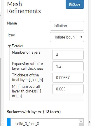
since solid_0_solid_0_face_12 is on the plane of symmetry. Shouldn’t that mean that it would never have any layering done to it ?

I even looked at all the control point of that face in Rhino and they are all at Y=0, so every part of that face should be at Y=0 and the plane of symmetry is Y=0…

Dale

Barry,

Notwithstanding Posts 10 and 11 which I think should be looked into (why is a surface on the plane of symmetry being layered?) I decided to start a clean sheet of paper for this mesh (sorry, if post 10 and 11 are to be looked into, you have the only copy of the project that still includes that meshing operation).

I deleted all my meshes and simulations from the project and only left the best geometry.

Then I used some meshing guidelines that I have been developing with Darrens help on another topic and which can be found here.

The results seem nothing less than spectacular so far (copy the project again if you wish), here is the y=-60 clip of ‘Mesh 1-4,685,530v 95.2 percent Inflated 40x20x26’:

I am simulating it now for a look at yPlus range but I expect good results with a 95.2% weighted inflation factor.

Keep your fingers crossed :smile:

Dale

1 Like

Well yPlus seemed nice and smooth with no deflations on Mesh 1 that I could tell, but I needed to get the minimum range up from 4 to 30 that I saw on it.

So, it looked like I need to redefine the inflation parameters to increase yPlus.

While I was trying to figure out why the first mesh yPlus range was so far off from the 160 average I was aiming for, I found out that when inputting the EWD from the online yPlus calculator to my spreadsheet, I left out a zero. Once I realized this I just fixed the parameter error I made in the Inflation parameter, re-meshed it to make the layers I thought I was making the first time and then ran the simulation again so I could inspect the yPlus range.

The mesh turned out to be a 90.2 % weighted inflation factor, lower than I wanted but I could see from the meshing log that the fuselage was only ~80% inflated. I decided to run a simulation anyway and have a look at the fuselage, I was surprised how good the yPlus surface mapping looked. I think I am happy with it.

This is my post processor procedure that I have ‘tweaked’ to get a nice mapped image range that means something (at least to me :slight_smile: 
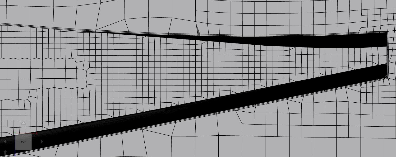
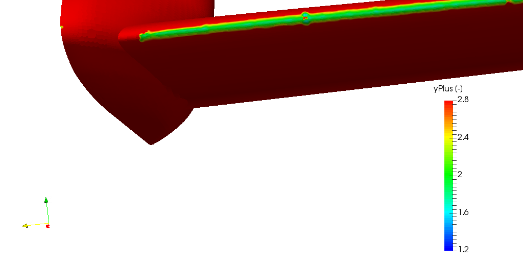
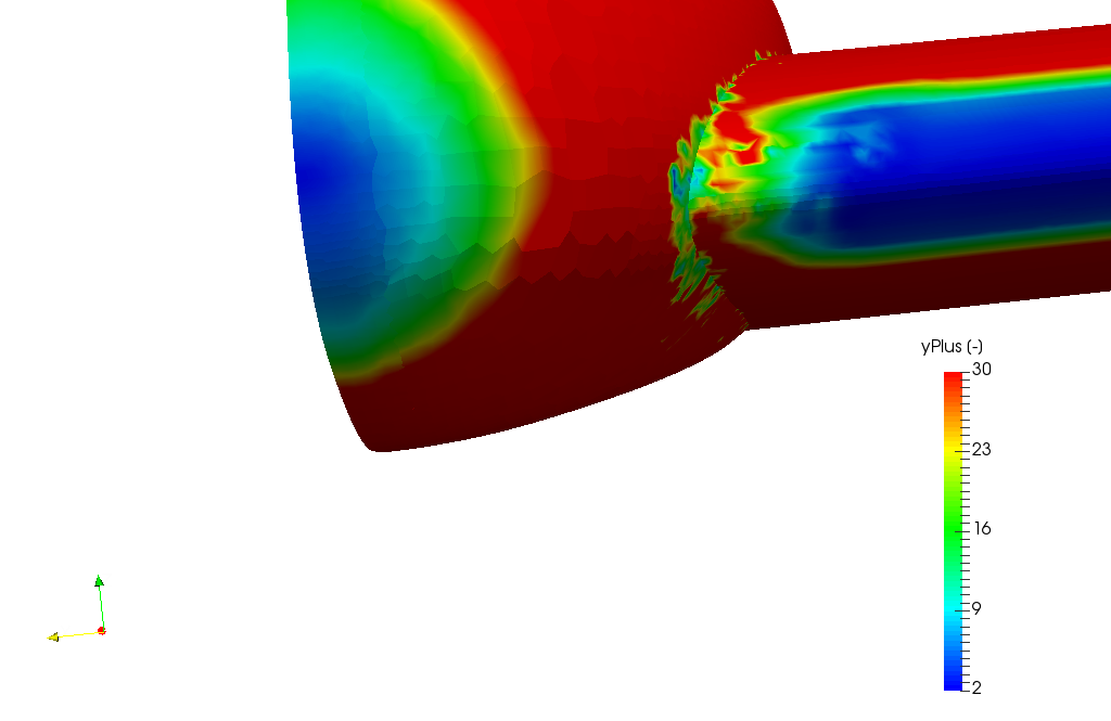
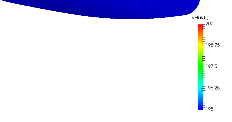
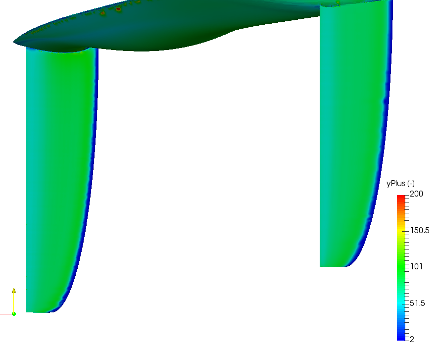
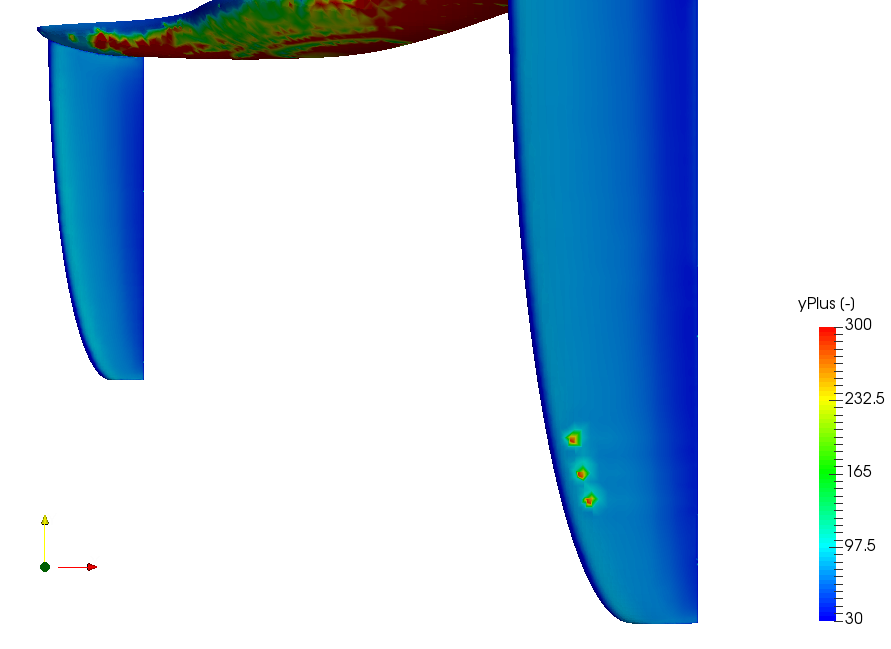
). First the auto range said something like 0.1 to 400, its was nice to know I am in the ballpark but I want to narrow that range so that I leave out that miniscule percentage of points near the max and the min that skews perception of the actual range.

Since I want a 30-300 range, I start looking at the values that are between 0.1 and 30. It turns out there really are not that many, mainly on the leading edge.

First I try to see when I start getting signs of areas of significant value density above 0.1. My first guess was 2, so I looked at a range of 1.2 to 2.8. From that I could tell that there were very few values below 1.2 because there were no dark blue areas on the leading edge. Since I do see a lot of green pixels I know they are around 2 and then the yellows are around 2.5 and then red is above 2.8. From this image I conclude that my data really starts about 2, not ~0.1:

Then I wanted to see what was between 2 and 30 so this is what that looks like (just to know what really is outside my range):

That is basically the low end values that are outside the 30-300 range, really a relatively small area on the whole plane.

Next I want to look at the high end. since the reported max was ~400, I just started whittling that down and increasing my minimum until I found the area on the fuselage that first started showing up as red, like this (really tiny red area on left):

So now I know my area of interest range is 2 to 200, like this:

And then finally, after doing the above, I think I can be relatively happy with my layering results, should I expect better?

Thanks
Dale

Hi @DaleKramer,

Looks like you are getting there in terms of layer generation! Layer generation is kind of an art, its not easy to get the optimal layers for every single part of the geometry, usually we aim to get it at the most critical parts and some less than ideal layers at less important parts is alright as you dont want to spend too much time on mesh generation.

So yes, I would say that the mesh looks good and its probably time for a simulation of that mesh. Do ensure that you’ve checked through the meshing log for illegal cells (ideally they should be zero) and the mesh quality check should be OK ideally as well but if its not, its alright (we may need to improve on it if the simulation does not go well).

Cheers.

Regards,
Barry

1 Like

Yes mesh has 0 illegal cells.

SimScale WB says ‘The mesh failed the quality test’, but I see that ALL the time… :face_with_raised_eyebrow:

To be able to see that yPlus range I had to do a full converged simulation and the results seem to be what I expected. At some point I will do a Mesh Independence Study to really determine if I can trust the results at this refinement.

Thanks for all the help,
Dale

1 Like