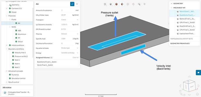
I am attempting to model the heat transfer due to the cooling fans in a gaming laptop using a conjugate heat transfer analysis.
I have used a velocity inlet and pressure outlet boundary condition for air yet get an error regarding the global continuity of the project, which recommends that I use pressure or velocity outlet boundary condition. Is the simulation not registering the pressure outlet?
Hi!
Could you please post a link (URL) of the project? Thanks!
You will find the error under run 1, thank you
Thanks. Velocity inlet + pressure outlet is indeed a good combination.
The issue here is that we have 2 separate flow regions, one of which has only 1 inlet, and the other has just 1 outlet:
In short, you should either have a single flow region with a pressure outlet and a velocity inlet OR have inlets and outlets for both fluid regions.
Cheers
That is extremely helpful, do you have any suggestions for how I can fix this and model the air moving through the interior of the laptop?
Do you know if the two fluid regions are connected? If they are, then you could simply use a boolean/union operation to combine them in a single part.
If they are currently not connected (but you would like them to be), then it will require some editing in a CAD tool to make a path connecting the 2 volumes.
What I am trying to do is simulate air being drawn through the “Back Vents” into the computer housing containing a CPU, GPU, heatsink and battery. The air is then allowed to leave through the underside vent where the pressure outlet boundary condition is currently placed.
In your opinion, what would be the best way to combine them?
Sorry, I could have been more clear in my previous message.
Are the 2 fluid regions currently connected in the CAD model? As in, do they connect with each other somewhere in CAD? If so, a boolean union operation will do the trick.
If they are not connected in the CAD model, then you would have to connect them somehow (how are they connected in your model? Try to replicate that in CAD).
For reference, note how this tutorial project has a single flow region: https://www.simscale.com/workbench/?pid=8039108563432137330
No problem I am new to Simscale in any case. The only way they are connected is that they both form part of the base of the laptop.
Hi, I have added a solid as an inner lining within the laptop which connects the two surfaces and thus serves as the flow region but my simulation is now giving me an error regarding the number of iterations. How can I rectify this?
Hi, I can’t find any simulation that failed with this error in your project, so it’s difficult to tell.
My first guess would be to double check the boundary conditions and make sure everything looks Ok. Try to open the results from the failed simulation and see if there are unphysical levels somewhere in the domain (e.g. super high velocities, negative pressure, negative absolute temperature).
The location of the error gives us some hints for troubleshooting.
Cheers
Hi, thank you for the reply. I had changed my geometry substantially.
I am now using a flow volume within the laptop, but I am now struggling to assign wall boundaries for heat flux for surfaces within the flow volume, how do I avoid this?

