This post is for a collaborative project started by SimScale user @tgulbinas
Short description:
- Internal turbulent flow
- Fan RPM = 20,000.
- Analysis Type: Incompressible turbulent steady state with rotation effect (MRF)
Problem description
Geometry modifications
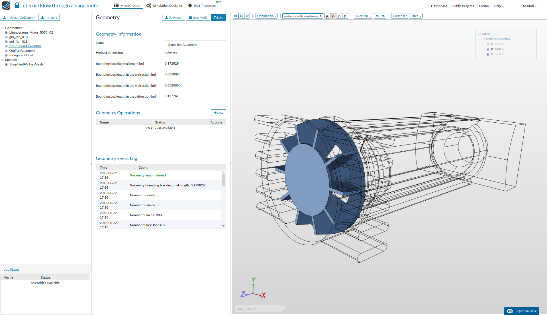
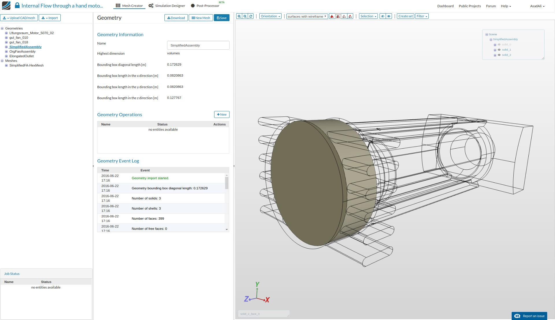
Two .step files for fan and housing were provided and first we need to make a single geometry file by importing fan into the housing geometry and placing it in proper position.
For the MRF mesh we need to make a cylindrical domain around the fan. This part will mimic the rotational effect of the fan.
Since in original fan housing, the gap between the outer and inner wall is very small. For the testing purposes we increased this gap a bit. For actual run geometry with original gap can be used
Now this single geometry, having three parts, can be used to make the MRF mesh.
Mesh setup
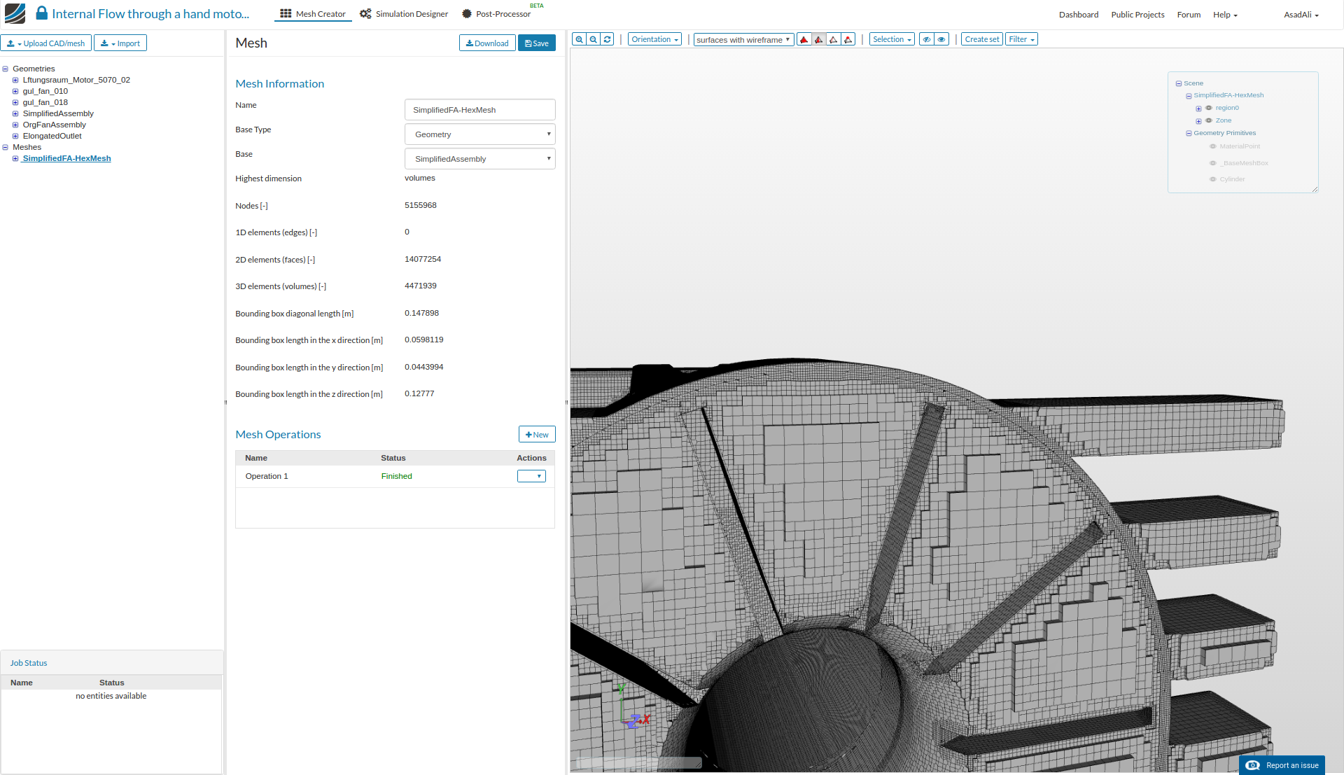
- Meshed the geometry using Hex-dominant parametric (only CFD)
- Surface refinements are used for fan and housing with different mesh refinement levels
- To create MRF zone(this zone will act as rotating part) another surface refinement is added with Create cellZone marked as true
- Other refinements are, Surface refinement for the thin housing walls and for outlets’ base wall
- Layers addition for better flow resolution near boundary
- Feature refinement to capture the geometry details near edges
- To further resolve the mesh at the MRF zone interface Region refinement is added which will resolve the mesh in both sides of interface
- Final mesh have around 4.5 million cells
- Mesh quality can be inspected by creating mesh clips at critical areas
- Rotating zone boundaries are resolved properly
- Housing thin walls have adequate cells to resolve the flow
- Fan is also properly meshed
For the simulation setup, parameters like the boundary conditions, inlet flow velocity or mas flow rate (corresponding to given RPM) are required. Once we have all these parameters we will proceed to the simulation.
2 Likes
@AsadAli and @tgulbinas - thanks for sharing, should be interesting to see the setup and the results!
Hello, thanks for the good work so far. The idea is that this is the inside of an electric motor in housing. The fan sucks air in through the red “AIR IN” windows, over the electric brushes (not in the model) - and along the inner rotor for cooling it and of course out through the green vents.
I don´t know how to determin other boundary conditions, inlet flow velocity or mas flow rate (corresponding to given RPM). Isn´t it possible just to spin the rotor and see what happens? Can someone help?
1 Like
@tgulbinas - Asad’s working on it, I’m sure he’ll let us know more this week
@tgulbinas
Well, fan has some angular velocity and this angular velocity determines the flow rate through the fan. The inlet flow rate should be more or less equal to this flow rate. The flow rate through fan can be approximated by the geometry of fan. Assuming, in one revolution, all the air across the volume between fan blades is pushed to the outlet, flow rate through fan can be approximated.
@Ali_Arafat Please have a look into the project
Hello, AsadAli. Sorry, but I don´t understand what you mean. What do we need? The mass/material of the fan? …the material is PA. Or the volume of air between the blades? The geometry is already in the model…
I would like to spin the fan with 20.000 rpm in the given space… see what happens and then change the fan and see what happens then. Is simscale capable of dooing this or not?
Hi @tgulbinas
For any internal flow simulation, the standard approach requires inlet or outlet flow rate or velocity.
As you do not have this value, we could try to use a so called ‘Open inlet’ . This approach will take more time as flow variables at the inlet/outlet boundaries are not known . I will setup such a trial case and get back to you with some results soon.
Best,
Ali
Hello @Ali_Arafat,
thank you for your fast answer. I look forward to it.
Best wishes
Timo