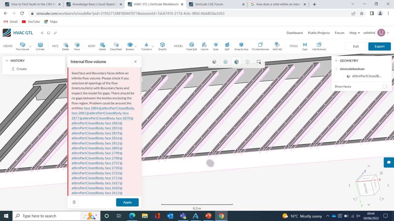
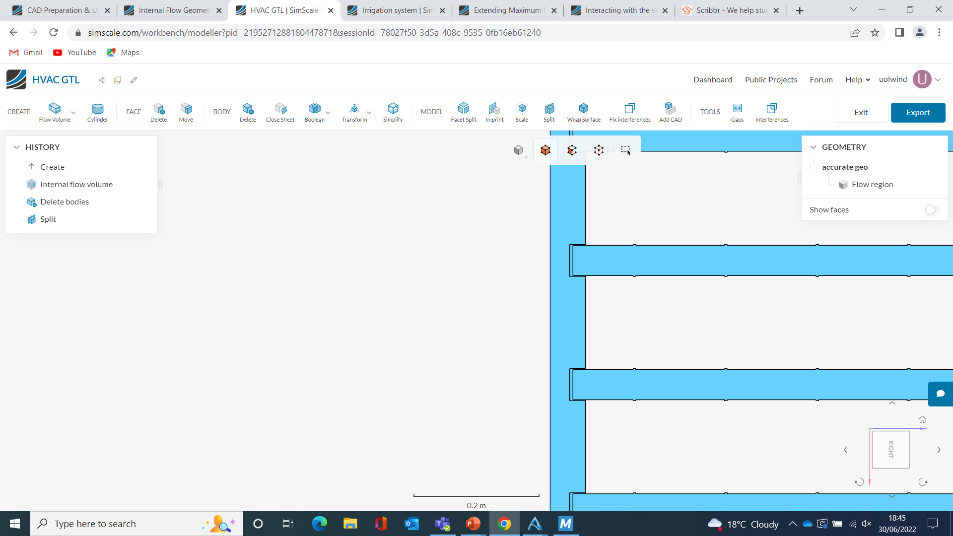
I am trying to model a complex HVAC system that has a structure more like a irrigation system. I want to be able to compare how different geometries effect the distribution of air. I am currently try to create the internal flow but keep getting the error message shown in the screenshot. Do anyone know how to solve this?
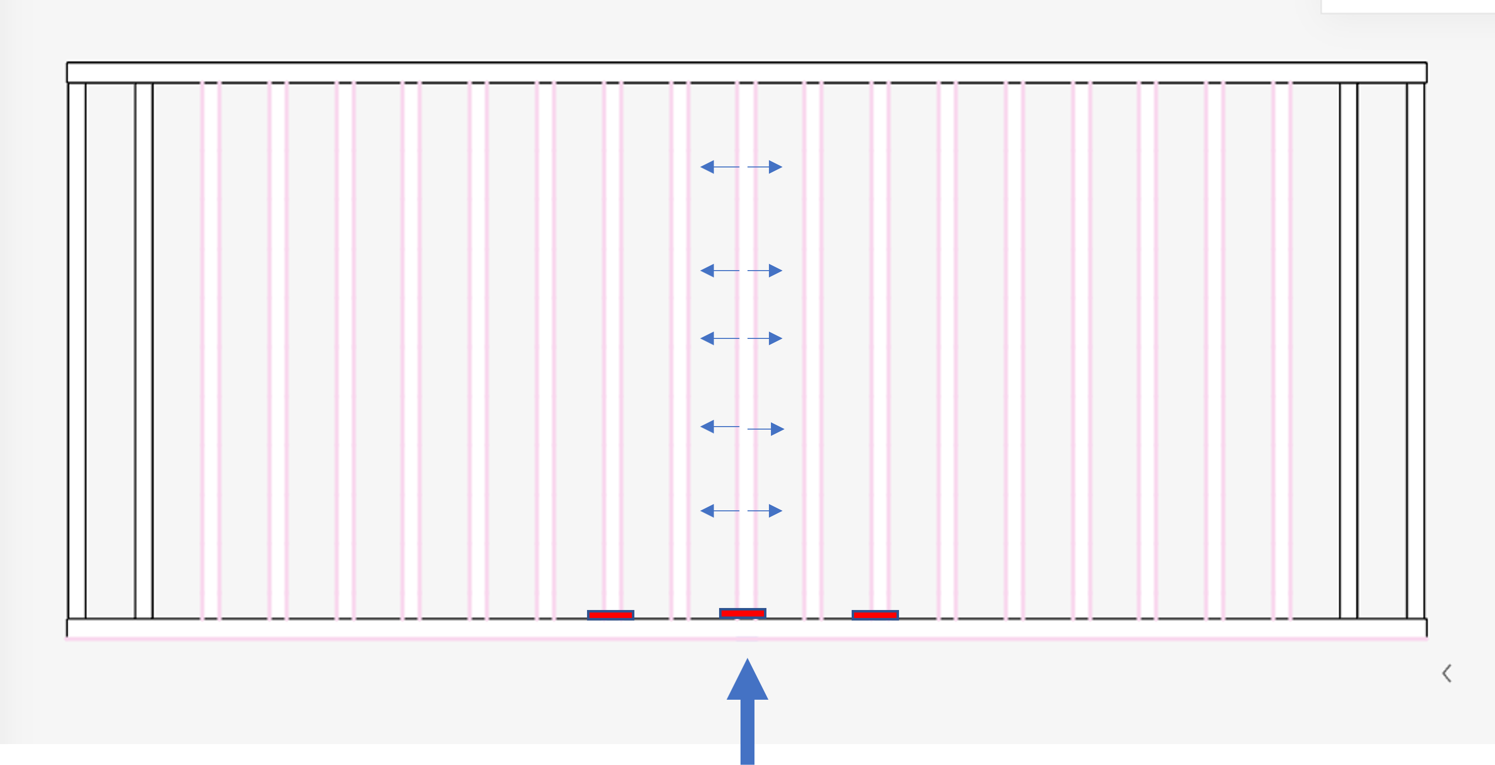
The small dots show all the outlets and the following screenshot shows what I want to model. The red rectangles represent caps that will block off ends of the tubes to determine which is the optimal configuration. The issues have started now that I’ve put these caps into the geometry. Any help or ideas would be much appreciated.
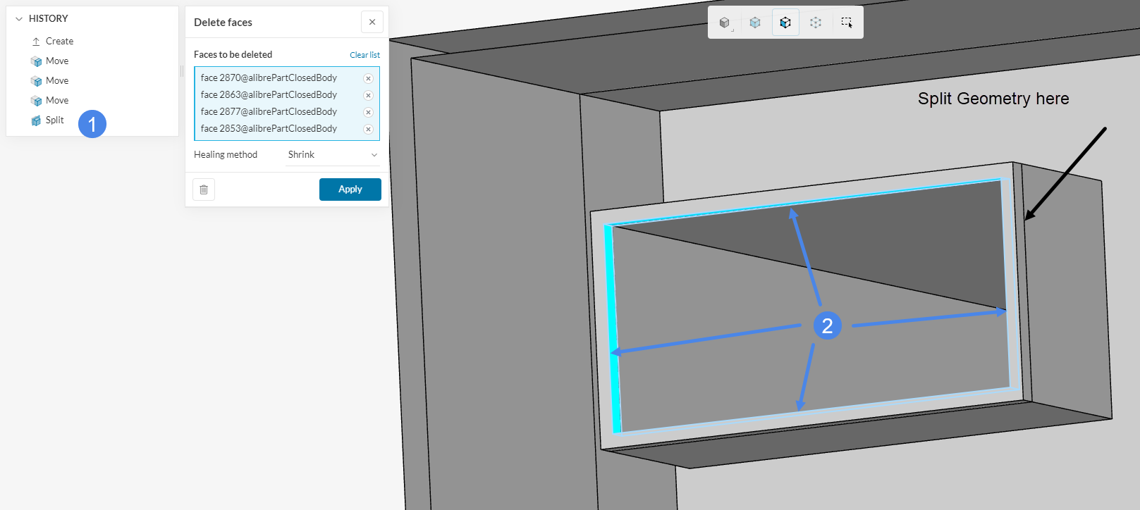
Can you please explain a bit further of what you mean with gab in the flow region.
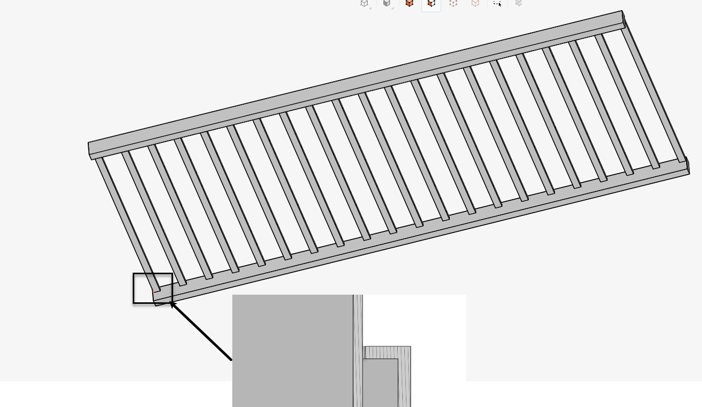
so the air should be leaking out between the long beam and the connecting part?
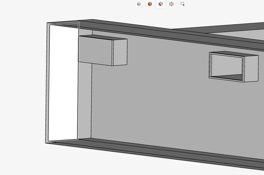
The air wouldn’t be leaking out, the flow should be blocked. So where that screen shot is there’s a cap on the end of the connecting part. This isn’t on all the connecting parts but it’s this feature that I want to test to see how the air flow can be more even throughout the system.
If you look at the first message the screenshot shows red blocks which is an example of where the caps might be. So the air would have to flow through the other pipes and round the other side to go the parts with caps on.