Hello. I am new to the simscale and the forum. For the past few days I tried to simulate oscillating metal block with a piece of rubber attached to it. I was hoping to see a wobble (deformation) of the rubber as it accelerates. I tried both dynamics and harmonic simulatitons with no sucess.
Could someone point me in the right direction and help me find what I am doing wrong?
Ben thank you for your suggestion, but I am afraid what you have done is not what I am looking for. In your simulation rubber is just uniformly affected by the gravity. I would like to see how the shape of the rubber will be changing in the initial let say 1s. Initially the whole thing is not moving. Then constant pressure (force) is applied to the carriage. As a result, carriage starts accelerating but due to the elastic properties of the rubber and inertia the top surface of the rubber falls behind. Eventually the top of the rubber accelerates. The rubber should be deformed at this time and should probably wobble relative to the carriage (top of the rubber should move back and forth relative to the bottom of the rubber) during acceleration.
In my simulation carriage is restrained in z and x direction but not in y. Pressure and expected acceleration are in y direction, which I thought should be OK.
I have managed to acheive something that makes a bit of sense but for the very short time (fraction of a mili second), but I can’t make it work over longer time. maybe I am doing something wrong with timesteps?
This is briliant. Exactly what I was trying to do. I still don’t understand why what I have done did not work, but I will study your example. this was just a little test for me to learn some basics of SimScale. Eventually, I want to use SimScale to simulate deformations of the core XY 3d printer that I am in a process of designing. I want to start with the y axis movement. Firstly, I will try to check if a linear rail is strong and stiff enough on its own or if I have to attach it to an aluminium extrusion. I will post my project when I make some progress.
How did you come up with you element sizing in meshing? Just trial and error, or is there a method or general rule that I should use.
The same question about second order mesh. How can one know which order should be used?
Lastly, what about damping coeffitients? Is there a place where I could find damping coeffitent values for common materials like aluminium and steel? I know, you did not use damping in this simple example, but I asume it it possible.
I used a mesh size that is about the thickness of the body to be meshed. The rubber is 3 mm thick and I chose a mesh size of 2 to 4 mm. This results in a pretty coarse mesh which runs quickly. However, if you are concerned about the accuracy of your results you should really do a mesh refinement study. This is were the mesh is made progressively finer until the results do no not change from one iteration to the next.
For structural simulations I always use a second order mesh. A first order mesh is quicker but will often result is stresses that are significantly lower than they should be. Please see this forum post for more details.
I have tried to use your example to do the simulation I was thinking about when I started testing simscale with the deformation of the rubber on an accelerating carriage. Unfortunately, I keep getting errors which I don’t understand. Would you mind having a look?
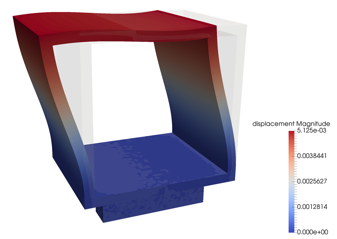
The main purpose of the simulation is to establish what sort of deformations an x axis rail of the core XY 3d printer will experience as a result of the acceleration of the y axis. I want to check if rail itself will provide enough stiffness or if it has to be attached to something like for example aluminium plate or extrusion.
Hi @witor, I’ve been trying to find the time to help you out but I’ve got a lot on my plate right now. I expect I can take a look at this in a week or so. If you need something sooner please let us know. Somebody else might be able to help you out.
Hi @witor,
just from a quick look at your setup of the dynamic case, I have two comments on how to improve it:
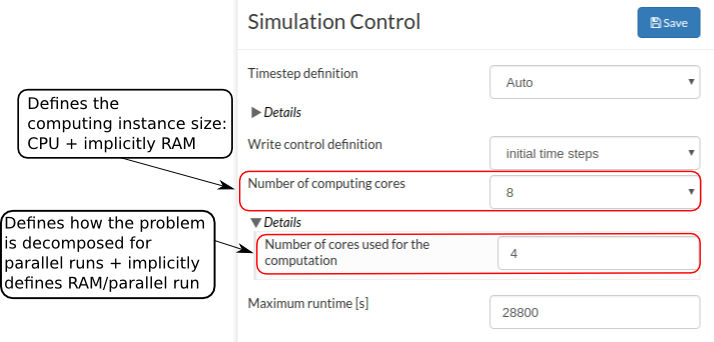
your failure comes from using a too small instance for such a large mesh. You should try to have ~ 50K nodes per computation core. In your case you have 425K nodes, but only selected a 2 core instance. The error should vanish once you select an 8 core machine
your applied displacement constraint seems to be a few orders of magnitude too big. You are applying a sinusoidal load with a magnitude of 0.5m, maybe you meant 0.5mm?
Hi @witor,
you are right, the error message and its recommendation is not very clear. Let my try to explain it.
Every time you start a simulation run on SimScale a cloud computing instance with the specifications as defined under the “Number of computing cores” is fired up. It defines how many cores the instance has and implicitly also how much RAM is available, according to this table: SimScale Documentation | Online Simulation Software | SimScale
For some solvers available in solid mechanics analysis types at SimScale (MUMPS and PETSC) the parallelization of the computation is done in a way that the initial computing domain (mesh) is divided into smaller chunks and on each one the solution is computed “independently” (not on the boundaries). This means the total available RAM is devided by the number of these parallel runs. This number is defined under “Number of cores used for the computation” (the wording is indeed misleading and we probably will change it). So, if your analysis runs out of Memory (RAM), there are essentially two options:
increase the available RAM on the machine (by increasing the "Number of computing cores) and leaving the “Number of cores used for the simulation” at the same level, or
leave the machine size at the same level and reduce the “Number of cores used for the Simulation”.
Of course this is only a simplification, as subdividing the computation domain into more partitions will also reduce the memory requirements to solve each domain as the get smaller, but this does not scale linearly.
Coming back to your problem. The above actually did not fully apply to your situation as you were using the MultFront solver, which does not use this kind of parallelization and is generally less memory efficient than MUMPS.
I made a copy of your problem and changed the solver to MUMPS and used a 32 core instance and it works just fine.
you can check out the project here: SimScale
I am totally blown away by SimScale, its capabilities and support. it is not the easiest to use for non-specialists like me, but it is not the fault of the software, but rather my lack of knowledge.
I really appreciate your help. It is amazing that one can simulate what will actually happen with the machine before even building it. In this particular case, I wanted to see if the linear rail on it’s own is stiff enough to withstand the accelerations without deforming. looks like it is but I found that extruder mounting palate should be a bit stiffer. Nice to be able to see that.