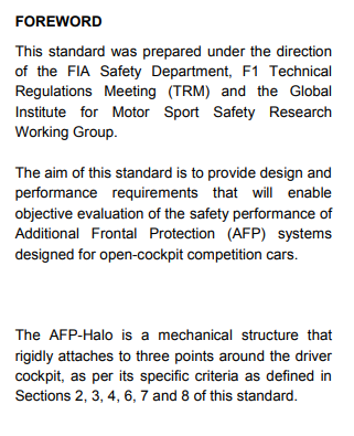
** Abstract:**
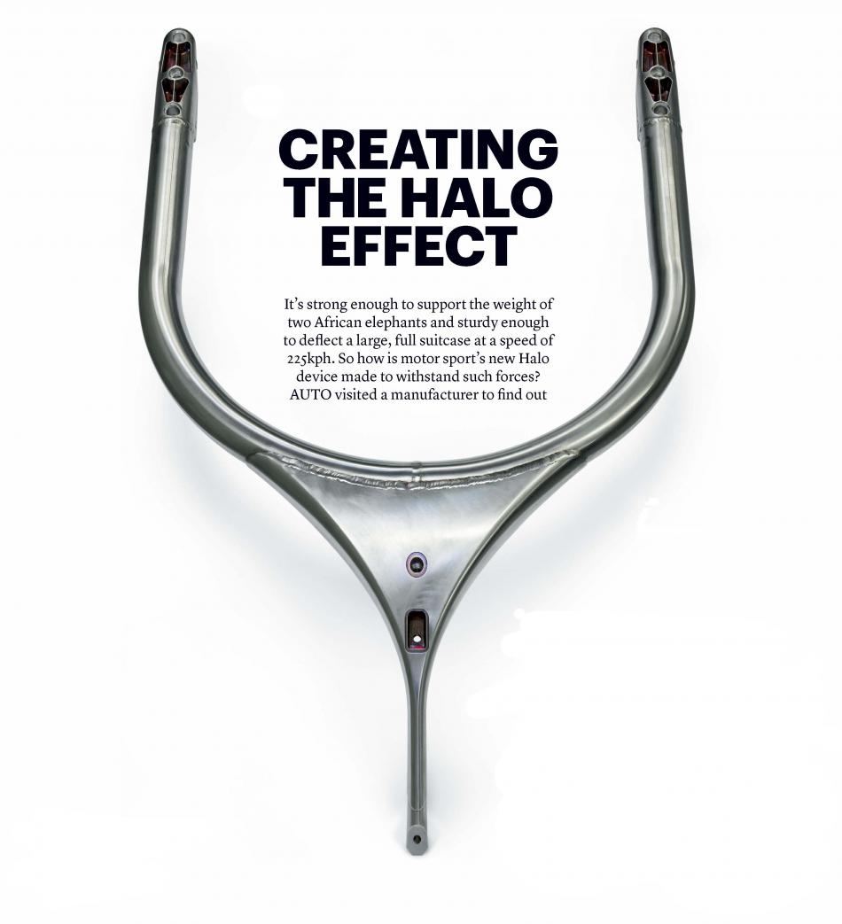
The halo is a driver crash protection system used in open-wheel racing series which consists of a curved bar placed to protect the driver’s head. The system was introduced in 2015 and became mandatory according to FIA homologation and regulation from 2018. The first tests with the prototypes equipped with the system were carried out in 2016 and in July 2017. Since the 2018 season, the FIA has made the halo mandatory on every vehicle in Formula 1, Formula 2 and Formula 3 as a new safety measure. In this project, F1 halo is simulated in two different static load condition and trying to find stress and total displacement on the surface.
Construction:-
The system consists of a bracket that surrounds the driver’s head and is connected at three points to the vehicle frame. The component is made of titanium and weighed around 7 kilograms in the version presented in 2016. The weight rose to 9 kilograms in 2017. The system is not developed by the teams, but is manufactured by three approved external manufacturers chosen by the FIA and is the same specification for all vehicles. In a simulation performed by the FIA, using the data of 40 real incidents, the use of the system led to a 17% theoretical increase in the survival rate of the driver.
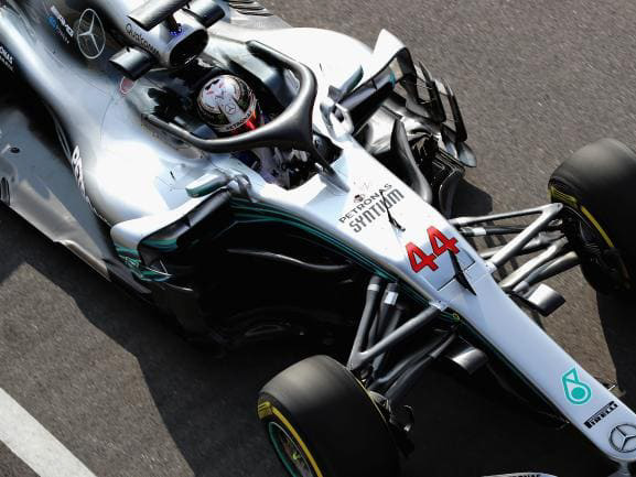
fig:- halo image
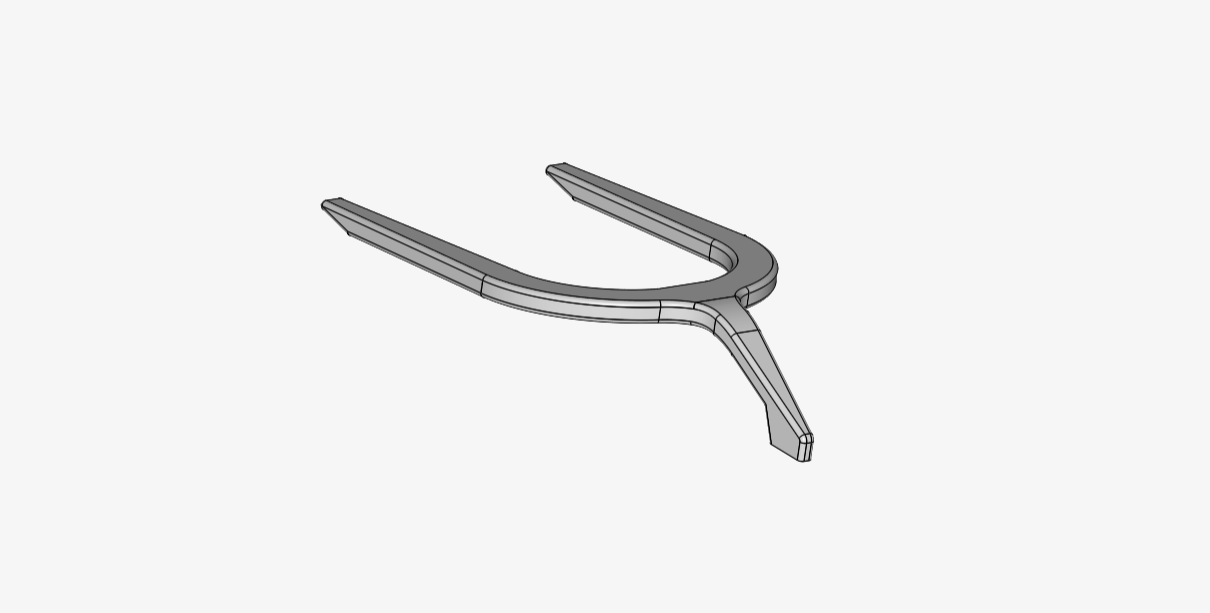
Fig:- Cad Model of halo
MESH:-
Meshing type =Tet-Dominant
sizing = Automatic mesh sizing
Fineness = very fine
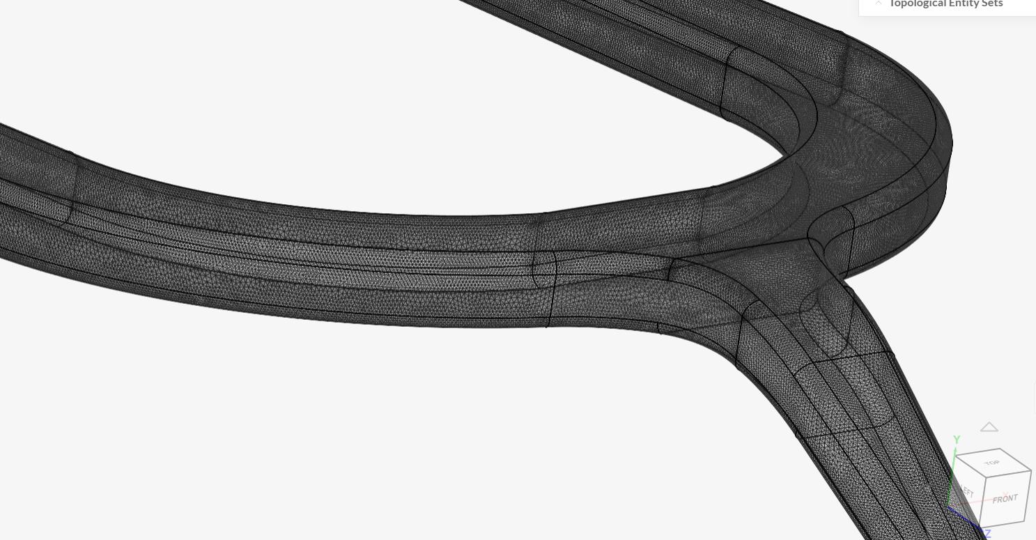
Fig: meshing of F1 Halo
Material :
It all starts with titanium. Lots of titanium.
“We had to buy about 10 tonnes of high-strength titanium within one-and-a-half months, and receive it all in time and in perfect quality,” says Steffen Zacharias of Germany’s CP Autosport, one of the three manufacturers chosen by the FIA as official suppliers of the new Halo safety device.
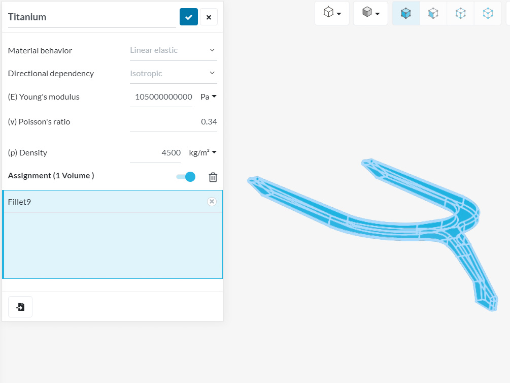
Fig: material apply to f1 Halo part
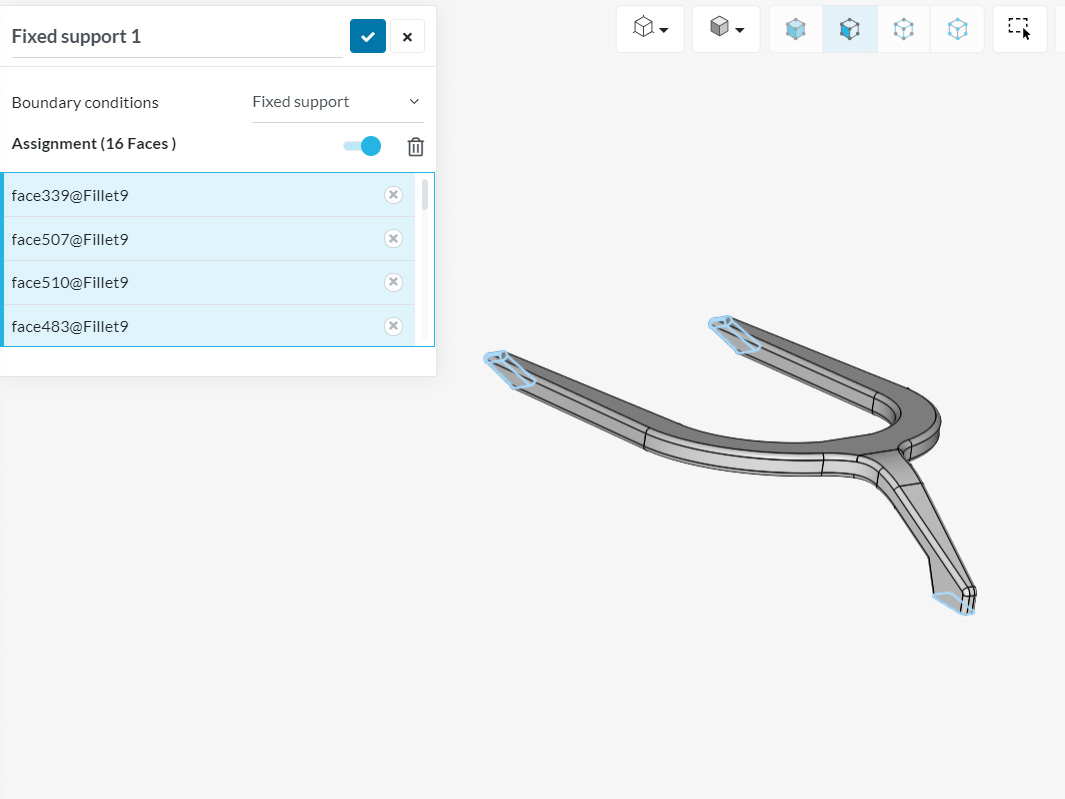
Boundary Condition:
-
fixed support:- in halo there is total 3 part which is connected to the frame of the car.
Fig: fixed support -
Static Test 1:
A load equivalent to 116kN vertically downward and 46kN longitudinally rearward must be applied at a position 190mm rearward of the front fixing axis and 170mm above the front fixing axis and positioned on the AFP center plane.
- There must be no structural failure of any
part of the structure. - When the applied load on the structure
has reached 125kN, the deflection must
not exceed 17.5mm. - Permanent deformation of the structure
must be less than 3mm after the applied
load has been released for 1 minute.
Permanent deformation will be assessed
by an appropriate dimensional
inspection
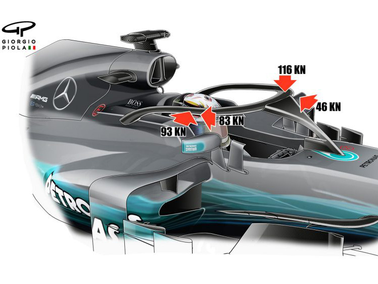

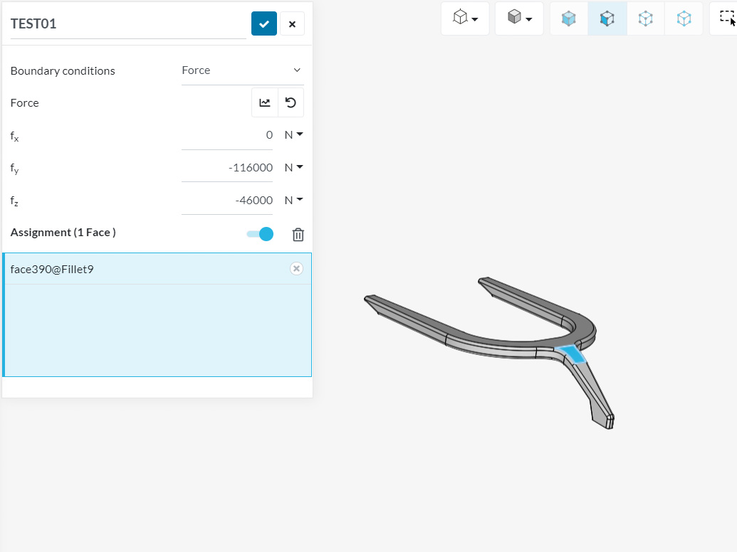
Fig: Static Test 1
3)Static Test 2:
A load shall be applied laterally inward and longitudinally rearward in an initial ratio of 1.12:1 respectively. This load must be horizontally applied at a position 385mm rearward of the front fixing axis and 150mm above the front fixing axis to the outer surface of the structure.
-
The peak load must not be less than
125kN. -
There must be no structural failure before
125kN. -
The deflection must not exceed 45mm
before 125kN.
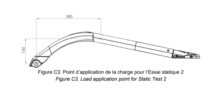
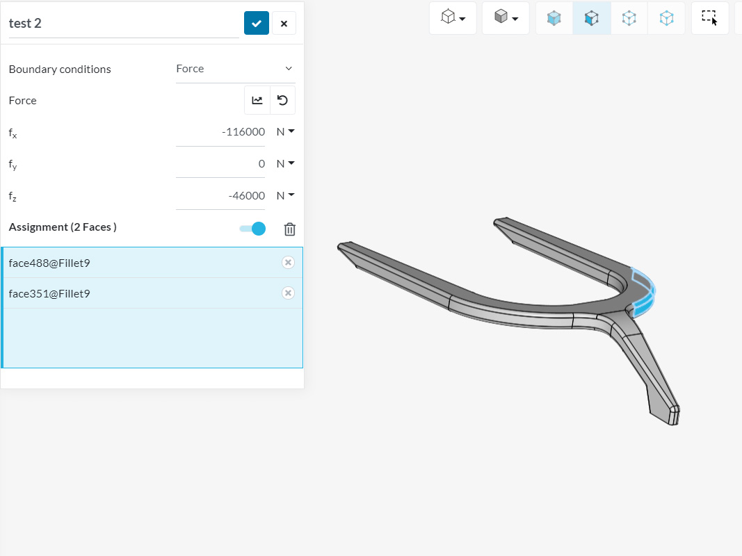
Fig: - Static Test 2
SIMULATION RESULTS:
1) Static Test 1:
F1 HAlo was practically simulated by the organization.
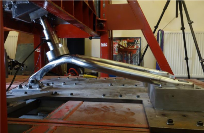
Fig: Halo on a Test bench.
Total Displacements results1:
2)Static Test 2:
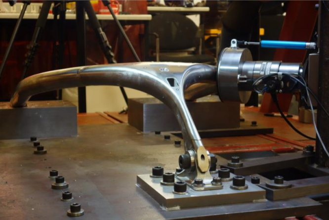
fig: Halo on a Test bench.
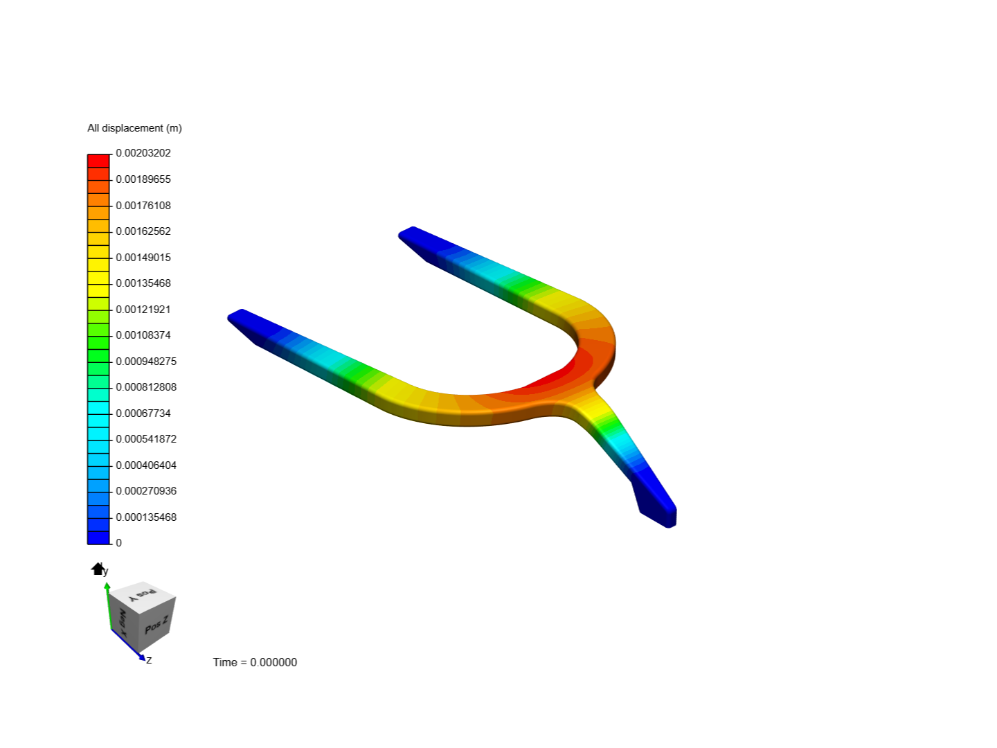
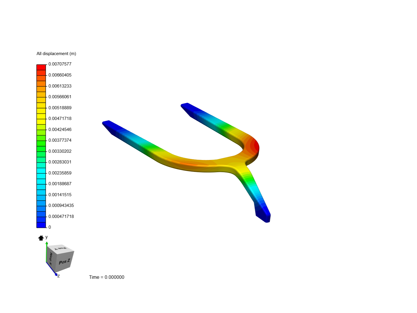
Total Displacements results 2:
Conclusion:
In Quasi-static Test 1 rule set by FIA was said “Permanent deformation of the structure must be less than 3mm after the applied load”. and from the above FEA Simulation static Test 1, the Maximum displacement of the object was 2.032 mm which was under the limit.
For Quasi-static Test 2 the maximum displacement of the part was 7.7577 mm which was under the limit of 45 mm before 125 KN load.
Impormants of F1 Halo:
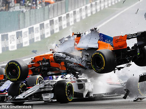
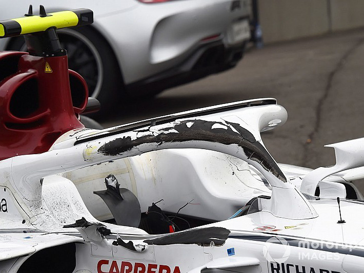
Fig: Leclerc car after crash
References :
1)Halo (safety device) - Wikipedia
2)https://www.fia.com/news/how-make-f1-halo
3)https://www.fia.com/sites/default/files/fia_standard_8869-2018_afp_v1_0.pdf
4)FIA working on new version of halo for 2021 with better appearance


 ? Its not mentioned in the pdf
 ) thus restricting all the 6 DOFs. So I don’t think that there will be a drastic affect of changing the current configuration and assigning new constraints.