Hi, I have run a CFD simulation over a car with the goal of finding the drag coefficient and calculating the drag force. The drag coefficient looks like it has converged and the forces in the direction of drag also look like they have converged. However, there is a lot of fluctuation in the convergence plots, especially the inlets and outlets convergence plots. I was closely following the “Incompressible CFD simulation over a vehicle” tutorial for my simulation and noticed that in the tutorial there was also some fluctuation in the inlet convergence plot especially (although not as much as in my simulation). I’m just wondering what the reason for the fluctuations in my simulation could be and also, since the drag coefficient itself looks like it has converged, is this value still trustworthy? It is lower than I think it should be. Thanks!
Hey there, and welcome to the forum!
Some possible causes for the fluctuation in the inlet/outlet residuals:
- Mesh is not fine enough.
- Model has not converged yet, needing more iterations.
- Boundaries are too close to the test body.
- Selection of boundary conditions.
- Numerics are too aggressive, with respect to relaxation factors.
You can test and improve all those aspects if you want to improve the residuals.
But from a practical point of view, I would take the forces if their graphs are converged. This indicates that the flow around the body is actually converged. At the inlets/outlets, perhaps one single cell which is not converged can cause the plots you are seeing, even though the majority of the flow is converged.
To build some trust on your results, I would:
- Check the y+ value:
- Perform some mesh independence analysis, by refining the the surface and close regions.
Ok great, thanks! I had made a copy of the project and tried refining the mesh and running more iterations but it didn’t appear to make much of a difference. If I want to use wall resolution instead of wall modelling how do I do this? And how do I find what I am currently using? I’m an absolute beginner at this, so am not sure whether I have used wall resolution or wall modelling?
Thanks!
I have just made it public. Project link: https://www.simscale.com/workbench/?pid=4590639385386615633&mi=spec%3Af8505ec5-cf97-421c-9207-1ad60d4e8494%2Cservice%3ASIMULATION%2Cstrategy%3A3
Thanks!
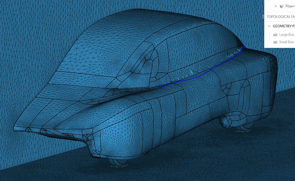
First i must say for a beginner you have done some great work! Did you model the geometry yourself because it looks really clean?
Just so you know you can make copies of meshes / simulations within a project, you dont need to make a new project. Copying mesh settings can make different setups much faster to run.
To answer your question directly:
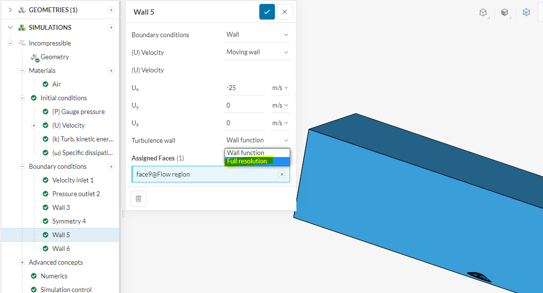
The difference between the two is that Wall modeling is defining a Y+ in the Log-Law region and Wall resolution is defining a Y+ in the viscous sub-layer or boundary layer. In short, since you are interested in drag, you want to simulate wall resolution or the viscous sub-layer. This means a target Y+ under 8 (preferably under 1). To calculate the needed Y+ it depends on simulation speed, air density etc… HERE is a good calculator.
This topic is very vast so i would recommend doing research on this.
You then adapt the amount/size of layers so that ALL Layers are under your Y+ of 1. To have successful BL inflation, try a test using 3 or 4 layers and increase from there. It is ALWAYS better in simulation to get things stable in the mesh on small test areas to avoid wasting time/core hours.
Two ways to make this happen.
- Growth rate
- First Layer Thickness - I prefer this method, there is more control of the first layer
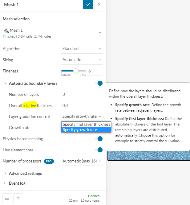
You also have to change all your No-Slip walls to measure in Full resolution mode (viscous sub-layer)
A couple of things to help you out not related to your question.
-
Add a local refinement to help reduce these bad mesh areas. You could also increase the mesh fineness on the hole car. (similar to what you did on the wheels
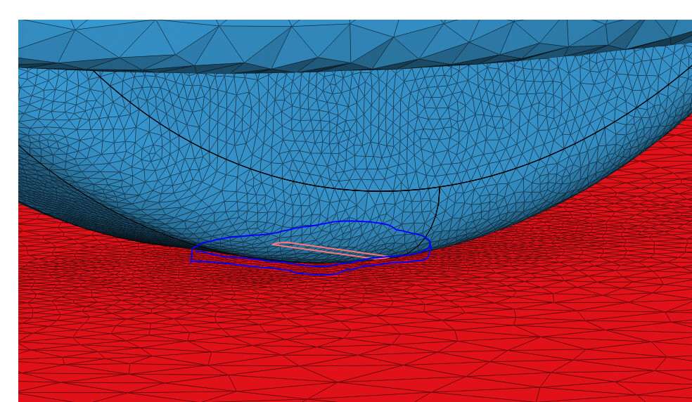
-
Sometimes you can get bad cells in areas with very sharp edges (where the wheels meet the floor) in your case you didnt but its common practice to cut the wheel away a bit (about 2-5mm) and add a pad so the mesh doesnt fail here.
-
This might be a little more advanced but realistically you need to have the wheels turning. If you modify the geometry to have a wheel well and full wheel then you can apply a rotating wall condition to get more realistic results
-
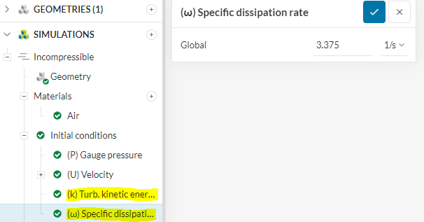
For K and W these values are normally calculated based on your bounding box size. this doesnt have to be super accurate but your bounding box is about the same that i use. so for K i use 0.06 and for W 44.7.
HERE is the calculation for it if you want. there is probably a calculator online
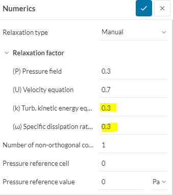
-
i normally have these on 0.7 each. Relaxation factors definitely affect convergence, look into this. Number of Orthogonal correctors is used when you have highly Non-ortho cells. you most likely dont need correction loops
Let me know if you have any questions
Good Luck,
Dan
Hi Dan,
The car geometry wasn’t actually made by me, but thanks! I’m trying to find the drag on this car, then edit the car to include some ducts, and simulate again to find the increase in drag.
Thanks so much for your help and suggestions, I’ll give it a go.
Cheers,
Josh