I am trying to get an idea of the maximum temperature of a chip on a heatsink.
I have been following this tutorial:
As far as I can see my project is setup as per the tutorial.
Running the simulation results in an error and I am not sure what to make of the error log.
Extract from the error log:
> Adding to radiations > Selecting radiationModel none > Adding fvOptions > No finite volume options present > *** Reading solid mesh thermophysical properties for region solid_2 > Adding to thermos
_> Selecting thermodynamics package _ > { > mixture pureMixture; > specie specie; > equationOfState rhoConst; > energy sensibleEnthalpy; > thermo hConst; > type heSolidThermo; > transport constIso; > } > Adding to radiations > Selecting radiationModel none > Adding fvOptions > No finite volume options present
_> → FOAM Warning : _ > From function writeOldTimesOnSignalFunctionObject::writeOldTimesOnSignalFunctionObject > in file misc/writeOldTimesOnSignal/writeOldTimesOnSignal.C at line 84 > ‘writeCurrent’ was set. This may lead to uncaught segmentation faults
_> → FOAM Warning : _ > From function writeOldTimesOnSignalFunctionObject::writeOldTimesOnSignalFunctionObject > [21] Set SIGFPE(8) signal handler > [22] Set SIGFPE(8) signal handler > [23] Set SIGFPE(8) signal handler > [23] Set SIGSEGV(11) signal handler > [23] Set SIGTERM(15) signal handler > [23] Set SIGQUIT(3) signal handler > in file misc/writeOldTimesOnSignal/writeOldTimesOnSignal.C at line 105 > sigTERM unset. Setting it to true so that signal is propagated to other processors > If this is undesired explicitly set ‘sigTERM false;’ in “system/controlDict.functions.sigHandler” > [0] Set SIGFPE(8) signal handler > To switch this off set ‘sigFPE false;’ > [0] Set SIGSEGV(11) signal handler > To switch this off set ‘sigSEGV false;’ > To catch Ctrl-C set ‘sigINT true;’ > [0] Set SIGTERM(15) signal handler > [0] Set SIGQUIT(3) signal handler > To catch the USR1-signal set ‘sigUSR1 true;’ > To catch the USR2-signal set ‘sigUSR2 true;’ > 4 signal handlers installed > Time = 1
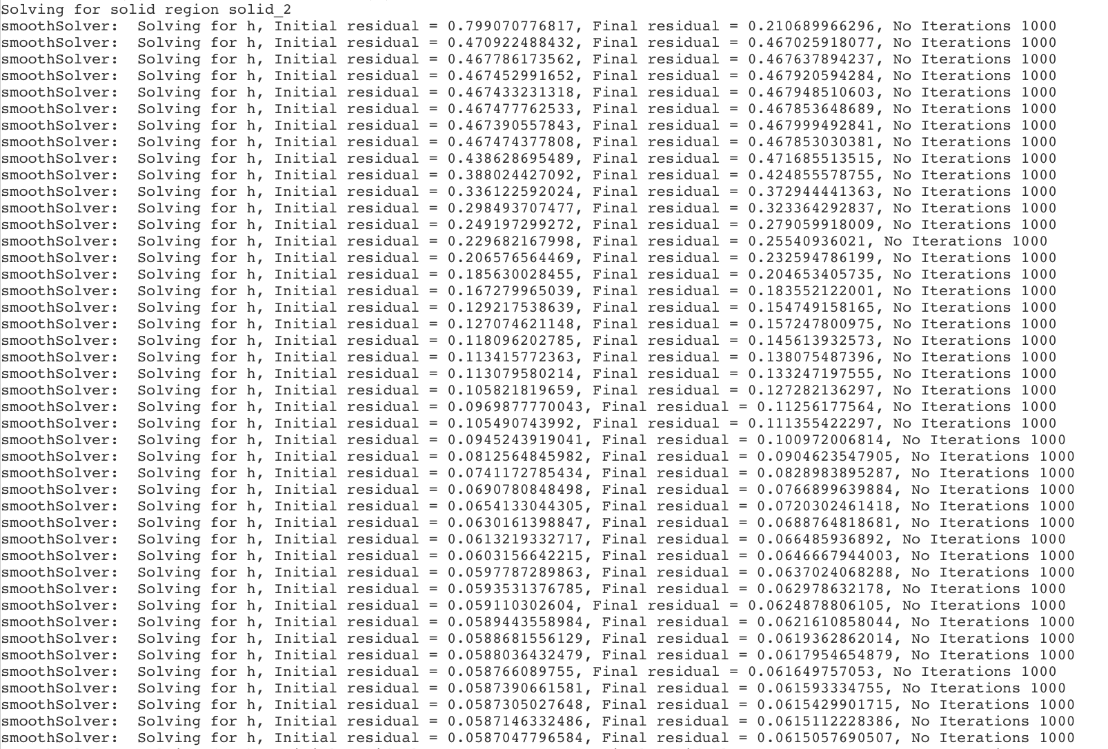
I got it solving by changing a few numerics settings, mainly the solid enthalpy solver to smooth solver.
By the looks of it, you might need to do a bit of work to get it to converge. Mine stopped after 500 minutes on 4 cores and was not even below 1e-3. but hopefully, this gets you unstuck?
Interesting application indeed! I see that you are performing a CHT analysis for which there is a prerequisite. Please note that the CAD should contain non-overlapping solid and fluid parts, but the boundary (interface) must be overlapping faces of the same area.
I see in the present CAD that the fluid (air region) is overlapping with the solids. A boolean operation in CAD tool can be done to get the necessary geometry. Please correct this model and proceed with the mesh operation. Once the CAD is according to specification then the interface detection in mesh log can be used to verify if things are properly in place before proceeding to the simulation setup.
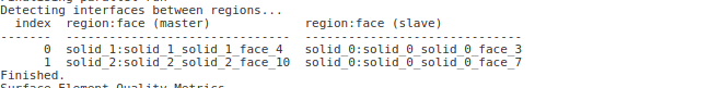
The current mesh has only two interfaces - one between solids 0 and 1, and other between solids 0 and 2.
I hope this helps! Good luck with the simulation and feel free to reach out for other queries
@sjesu_rajendra, can I also just ask a quick question on this. When I was solving there were many enthalpy solves for each of the solids, why does this happen and can the number of times it is solved be controlled?
Hi Darren and Sam,
Thank you for this. This has at least got it solving. Do you know of any good resources on how to setup the numerics?
My next problem is the CAD itself as Sam has pointed out.
My CAD contained overlapping regions of solid and fluid parts and the interfaces between the parts were not being identified. So it was just my understanding of how to prepare the CAD models for the simulation.

 Would be awesome!