I am trying to simulate heat transfer using CHT from a solid copper pipe to a fluid (water). I created my curved pipe geometry using SolidWorks and imported as a STEP File. I used Hex Dominant Parametric for Meshing.
I feel like I’m doing something wrong with the simulation as the heat is not being absorbed by the fluid. Appreciate if someone could go through the case and advice on what I should change in order to run the sim correctly.
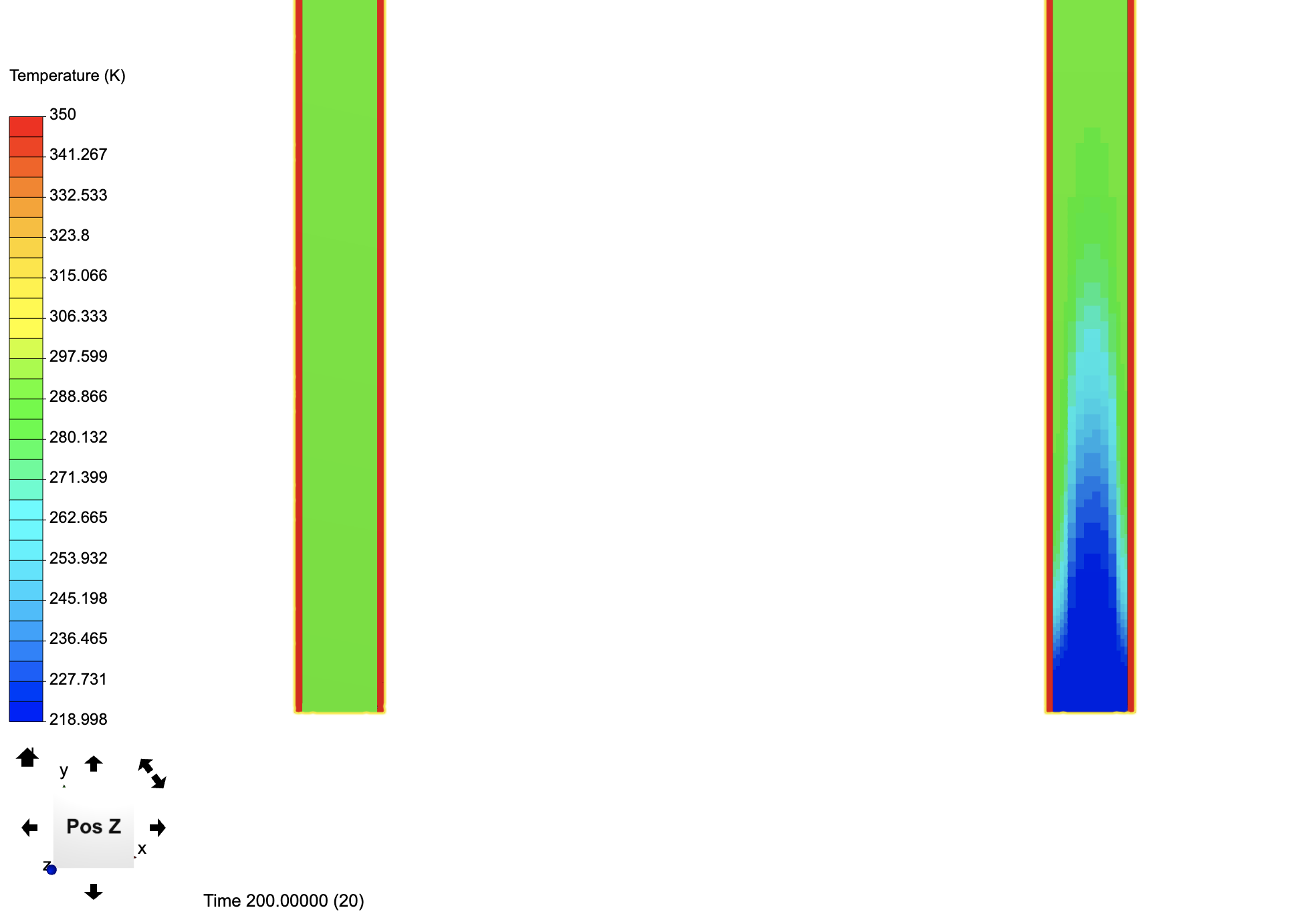
I have changed the temperature if the velocity inlet being different from the initial boundary temperature of the outer wall and got the following results.
You can further improve the mesh as well as add inflation layers for the pipe to be more “realistic”. Also do not worry about the representation of the temperature here - to get a smoother plot simply use temperature [node]. Maybe adapt some settings and let me know how things go!
Thank you so much for your support @jousefm . This is actually a small portion of a large geometry but the same working principle. I will re-do the meshing and run the simulation again as per your instruction.
Hi @jousefm! I meshed another geometry using the Hex Dominant Parametric. But there is some error in Meshing, appreciate if you could and advice on what parameter should I change in order to get a finer mesh. I also have attached the screenshot.
From this, I would like to study the heat distribution when heat is applied on top of the plate and cold fluid flows through the serpentine tube.
That’s because the number of cells across the z-axis is too low. I am currently trying to set up a new mesh that would overcome this problem and let you know once it has finished
Just wanted to ask if you have some data on this project or just want to test it? The thing is that the meshing will be super big and with 16 cores you would not be able to simulate it - you would need at least 32 cores for the meshing only. Other than that the aspect ratio of your model causes these “holes” in the pipe geometry so we could make sure to increase the height of the solid block if that is applicable in your case. The more input information you have about the case the better.
Hi @jousefm! Yes, this geometry is based on a research journal but it was done in ANSYS (I can share the journal with you if needed). Basically, as a part of my MSc thesis, I have to simulate this geometry and validate the result with my own research. Yes, I faced the same problem when I try to mesh because the number of cores isn’t enough. I tried to mesh only the serpentine tube without the plate by increasing the height of the block, but I still the same error that the computational power isn’t enough. Is there any alternative solution for this?