I am following the “Conjugate Heat Transfer: Cooling of electronic sink”. I designed a semi circle pipe with one fluid region and one solid region in catia. After I imported it in SImscale in solid domain there is a face divided by sharp angle in solid region. I don’t know how to remove it. Anyway I created the "Hex-dominant (Only CFD)Automatic mesh. I followed the similar to “Conjugate Heat Transfer: Cooling of electronic sink” expect I didn’t give initial condition. But the simulation is running very long time and i tried few times but it didn’t finish.
Could someone check it and let me know the mistakes?
Based on your latest run, the sim is running fine. Just got to let it finish. Though you did set an end time of 4000s which may be too long. You might want to start with 1000s first and see if it converges.
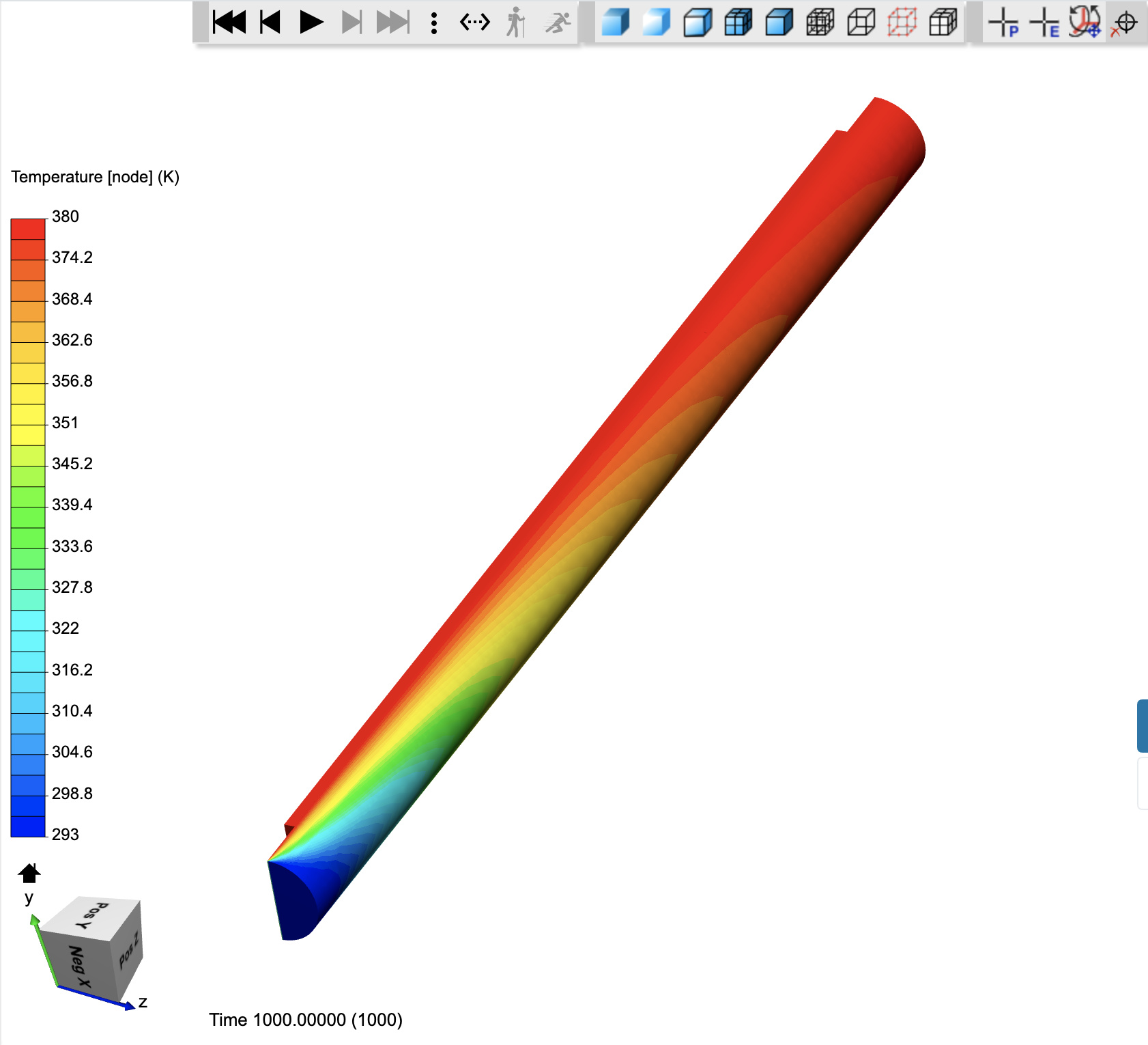
Thanks for your quick response. The simulation is finished and the set an end time of 4000s. But there is no heat transfer between solid and fluid. I don’t understand where is the problem. Could you check it and let me know?
Yes, The simulation stopped in middle and there is no heat transfer between fluid and solid. And I have problem in interface.
Detecting interfaces between regions…
The following face pairs are only in partial contact and are not imposed as automatic interfaces.
Please add these interfaces in the simulation setup if you are sure that they should be introduced.
Note that interfaces are supposed to be exactly matching. Otherwise results might be wrong.
You can ensure exactly matching interfaces by imprinting your model in your CAD environment:
index region:face region:face
Detected 0 valid interfaces. 0 interfaces failed to be resolved with the applied mesh fineness.
1 interfaces are only partial and are not taken into account.
HybridBody 1: face 15 is in Fluid domain and GSMExtruder2: face254 is in Solid domain. I don’t know how to fix this problem!
After you ensure that the geometry are separate but connected faces then try to remesh again and check on the log to ensure this error does not pop up again.
I tried to correct that face in geometry. I draw the geometry with two separate region in Catia and imported to Simscale. But after I imported the geometry in Simscale it’s showing only one region or two region with error in the face. You can understand if you check the project.
For Heat transfer problem I need two region, One is Fluid (Water) another one is Solid (Aluminum). So I don’t know how to solve this problem in Simscale.
can you share a screenshot of that issue? Checked your project link at the very top and could not see any issue with the geometry - you have to make sure that the surfaces touch and can actually check if there’s anything wrong with the geometry by looking at the Meshing Log. More information can be found here: CHT - Electronics Cooling.
I imported two geometry for same project in SImscale. One is “Pipe with one Solid” another one is “Pipe with two solid”. Both geometry are same and I changed the way to draw in Catia. Basically the project is heat transfer from Aluminium wall to water. I am following CHT - Electronics Cooling . project as reference.
First geometry “Pipe with one solid” is perfect for meshing. But there is only one region after I imported the geometry in Simscale. I don’t know why is not considering the geometry with two different domain. So I can’t use this geometry for heat transfer analysis between Aluminium and water.
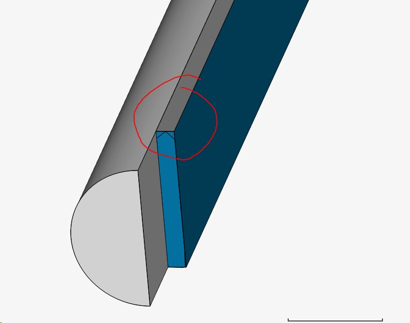
I imported the second geometry in Simscale and it’s have two solid region (HybridBody 1 and GSMExtrude 2) . But in GSMEctrude 2 solid region there is sharp face edge. I don’t know how to correct it. Anyway I started to meshing it and it’s done with following error
Detecting interfaces between regions…
The following face pairs are only in partial contact and are not imposed as automatic interfaces.
Please add these interfaces in the simulation setup if you are sure that they should be introduced.
Note that interfaces are supposed to be exactly matching. Otherwise results might be wrong.
You can ensure exactly matching interfaces by imprinting your model in your CAD environment:
index region:face region:face
Detected 0 valid interfaces. 0 interfaces failed to be resolved with the applied mesh fineness.
1 interfaces are only partial and are not taken into account.
HybridBody 1: face 15 is in Fluid domain and GSMExtruder2: face254 is in Solid domain. I don’t know how to fix this problem!
Then I started the simulation for “Pipe with two solid” but there is no heat transfer and it’s stop in middle.
Might be that there is no connection between the surfaces which is the most obvious reason or the mesh is not good enough to snap the two affected surfaces together. Will check it out as soon as possible and let you know!
The only thing I changed was to add one connection to snap together both surfaces between solid and fluid for heat transfer to take place. Other than that I just played a bit with the numerics of the enthalpy (namely error) which seemed to have no effect on the results whatsoever.
P.S.: Before I forget to say it. You also have to make sure if you add boundary layer inflations and check the y+ value in the post-processing. Maybe @Get_Barried and @DaleKramer can add their thoughts here.
I followed your steps in project [Deleted by author] to try myself.
Did you use “Prio - Automatic Mesh with Imprint” mesh to simulate right? How did you create or generate “Imrint” in Geometry? There is different between Geometry Event log in your method and mine.
I tried to solve this different using scaling (Scale Factor 0.01) and I removed the sharp edge (see the picture) problem in geometry.
Now the geometry seems perfect. However still there is different in geometry event log in your method and mine.
In Meshing I followed your step, So I created Fluid & Solid Surface refinement and Inflate boundary layer 1 for surface “face25@HybridBody1” in Refinements. Then I started the mesh. But still it’s showing
“Partial interfaces were detected that are not taken into account. Please check the Meshing Log for more info.”
I don’t know what I am missing from your step. Is there problem in Geometry event log or problem the way I am meshing? Could you please look my method and tell me what’s the mistake?
No worries about different logs. I used this option as I have a hidden option to do so but you can do the same by using Onshape it is not hard. You simply have to split the big surface with the smaller one choosing the side faces to make sure the bigger surface is split into three parts as you can see in my simulation. That’s just to let the mesher know that the surfaces are identical (and touching) otherwise it will always fail to capture the interface between solid and fluid.