Let’s discuss a basic check list to troubleshoot or verify your rotating machinery simulation setup.
A successful simulation setup starts with a good (simulation ready)CAD model. - When it comes to a rotating machinery simulation within SimScale, it is encouraged to check our article on “How to prepare a CAD for simulating rotating zone”
Once the CAD is ready, there are few checks you can do to make sure your setup is valid:
-
Checking if your model has the flow volume create along with an overlapping solid body that encloses the rotating zone
-
Check if the Fluid material is assigned only to the flow region
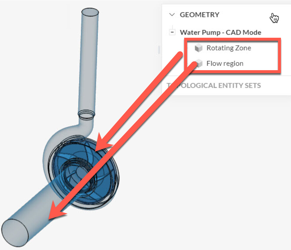
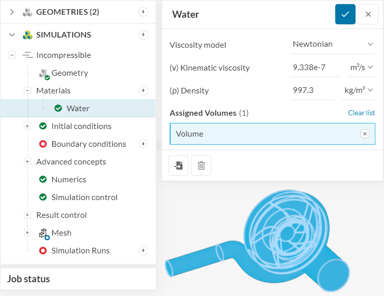
(The additional Volume / Solid modeled for Rotating zone should not be assigned with any material properties)
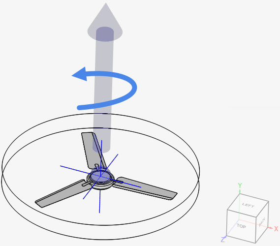
- Check if the Rotating zone is assigned under the Advanced concepts:
-
a) Assigning the rotating zone with correct “Rotational Speed”. (In SimScale you would be able to set the rotating speed using two different units - rad/s or °/s)
-
b) Check if your Rotational axis is set correctly. The rotational direction follows a Right hand thumb rule.
-
c) Check if the Origin is set correctly. Key is to set this point on the axis of the rotation and in most cases it is preferred to set the origin as the centroid of the rotating part (Impeller, fan, turbine, etc.,)
-
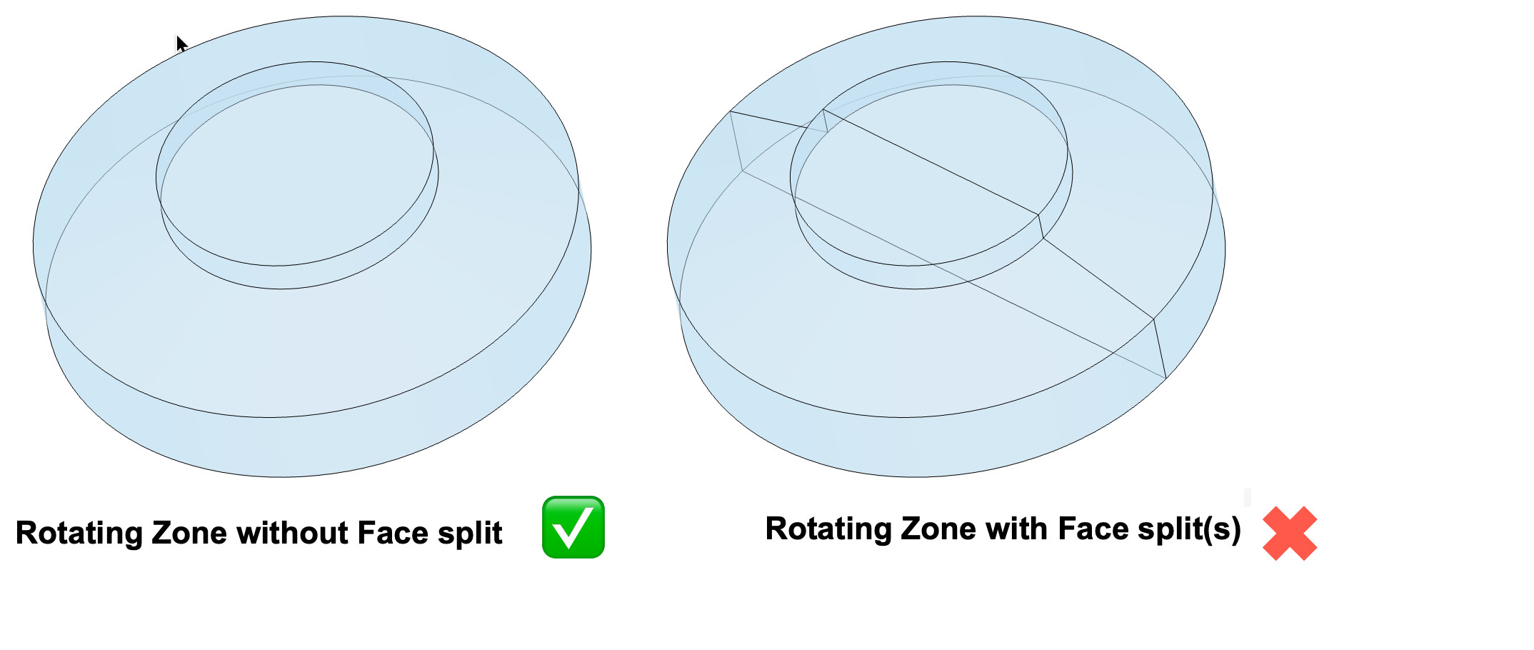
Specific to the analysis type : Subsonic
If you are using our Subsonic analysis type, there are a few pit falls that you can run into.
a) The Rotating zone should consist of a single face along the circumference. A split face in the rotating zone might cause unnecessary issue during the mesh and simulation.
Note: This post focusses specifically on a Rotating machinery simulation and some of the points discussed here would be valid for any general simulation as well.