Hai @Retsam… Not sure what I did wrong… in this project…the first simulation I ran … led to error ( telling me remove boundary layer condition) so I removed the inflate boundary layer refinement in mesh and ran 2nd simulation (labed as copy of 1st simulation in workbench)… one thing to note is that I add force and moment on the entire blade…can you help me identify mistake
Thank you
Hi @mnoor_mohamed:
For Materials (Water) you need to point only to your Water volume, not to MRF zone.
But the main problem for internal CFD is that message from Simulation: “A multi-region mesh was assigned - this analysis-type requires a single-region mesh.” This is linked to your mesh parameters for MRF. It should be defined in Surface refinement ‘With Cell zones’. This is not the case now.
Cheers,
Retsam
2 Likes
Thank you  …I will apply changes and try
The error came changed not enough memory usage then i added inflate boundary layer boundary condition …then also the mesh was not generated… now i changed mesh fineness to very coarse and started the mesh… any thing i can try changing …can u suggest anything …thank you 
@mnoor_mohamed: your mesh log reports you have many (too many) errors.
Checking final mesh ...
Checking faces in error :
    non-orthogonality > 70  degrees                        : 110
    faces with face pyramid volume < 1e-20                 : 0
    faces with concavity > 80  degrees                     : 0
    faces with skewness > 4   (internal) or 20  (boundary) : 0
    faces with interpolation weights (0..1)  < 0.02        : 27
    faces with volume ratio of neighbour cells < 0.01      : 2165
    faces with face twist < 0.01                           : 5
    faces on cells with determinant < 0.001                : 0
Finished meshing with 2307 illegal faces (concave, zero area or negative cell pyramid volume)
Finished meshing in = 681.71 s.
You have to work on it: try first do not use BLs.
In Advanced concepts you did define MRF zone on correct Z axis, but MRF is not rotating: perhaps it is on purpose?
Hai… @Retsam and @jousefm …I created a different model … meshing n simulation was successful…
Can tell me how to slow the animations of stream line animation to be presentable …to be used in ppt.
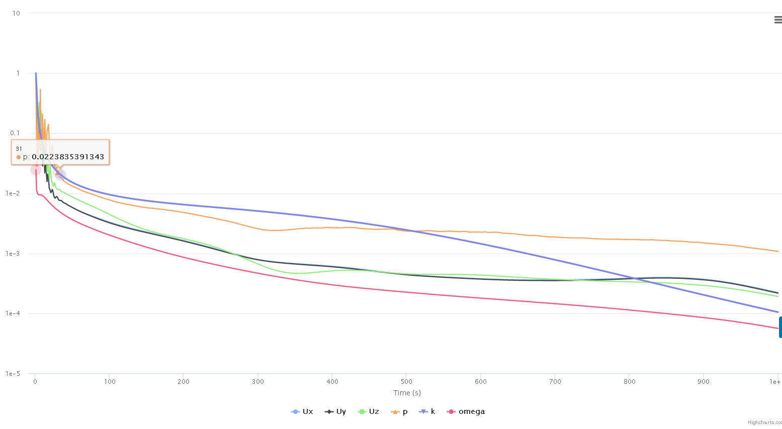
And also ur opinion on the stability of the result … Thank you
Hello,
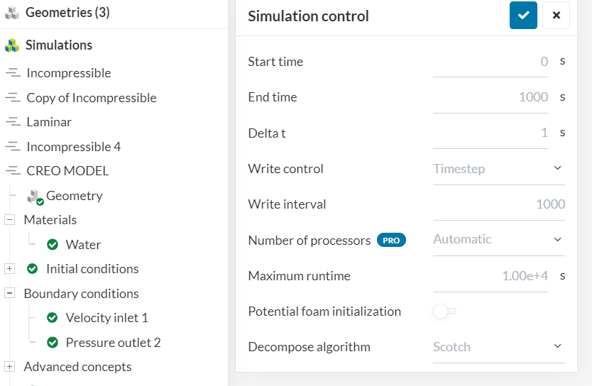
In Simulation control panel, you need to set Write interval to, for example, 200 seconds. That way you will have few snapshot which can be a base for animation when in ‘Solution Fields’ .
For your simulation I suggest you also use ‘Potential foam initialisation’, which should accelerate convergence (which is still rather bad in your case).
Cheers,
Retsam
Thank you I would implement for next simulation…
this question can be silly…but just to clarify…when i did my cad model i moved it away from origin… so while defining MRF ZONE the axis of rotation and origin is away from my model …
Should I change the origin to center closer to flow domain and should I also change the axis of rotation to inclined in angle since turbine is slanted…or should I leave to downward z direction ?
Should I leave to default ??
Hi @mnoor_mohamed: Currently your flow is oriented on Z axis, origin of rotation (MRF) should by the geometric center of MRF cylinder. You need to check in your CAD, if MRF cylinder center is on 0, 0 (X, Y).
In your simulation case, there is no way to indicate ‘slanted’ operation. That flow is vertical or horizontal: inflow is 0.1 m/s and this is the initial value flow speed. MRF rotating 50 Rad/s seems very high in that respect…
Cheers,
Retsam
1 Like