CAD issues for CFD analysis

@lisandromaders,

thanks for providing me with the project - I checked on it in more detail and I think I found the reason: The solids in this assembly do intersect with each other. This means there are certain faces that are overlapping with each other. For the hex-dominant snappyHexMesh mesher on SimScale this is a problem. The reason why this is a problem is a bit longer to explain and I am thinking of putting an article together for the documentation - also @Maciek wrote some interesting questions regarding snappyHexMesh in this post.

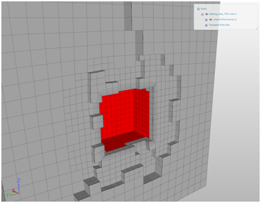
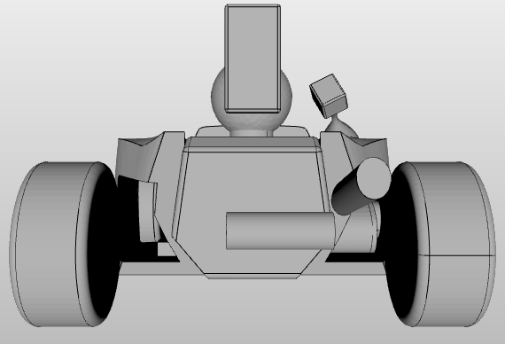
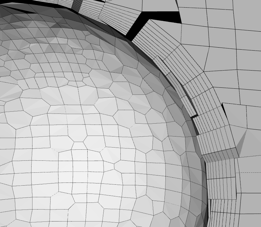
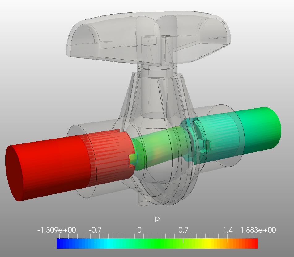
For the time being let’s first concentrate on how to fix this: I think it’s these faces:

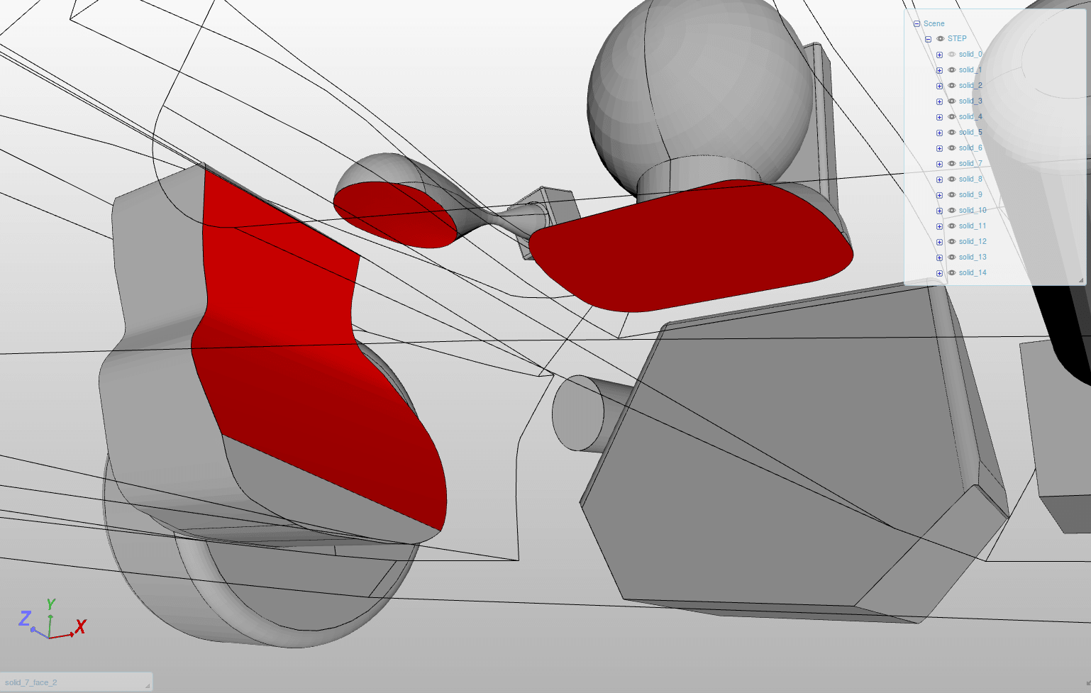
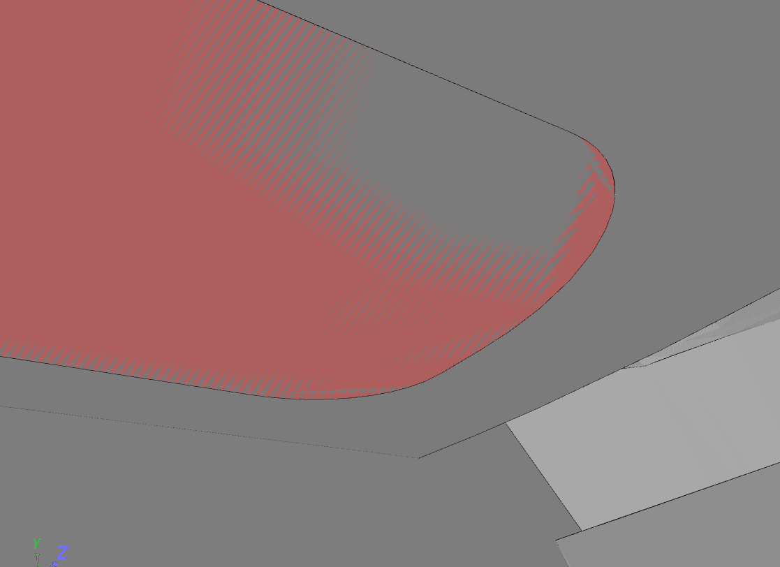
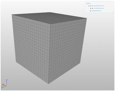
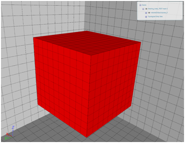
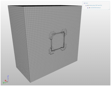
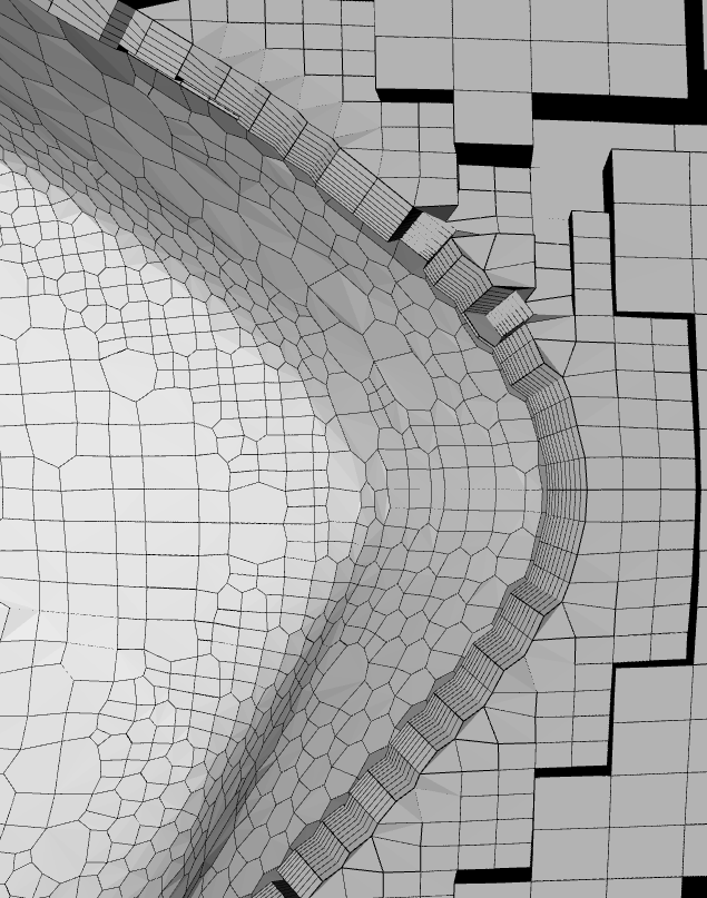
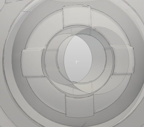
They do exactly overlap with the actual chassis (hidden in this image). This shows it from another view:

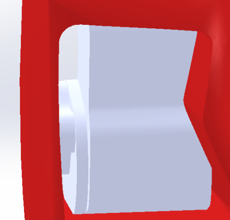
This solid basically has one face that is completely overlapping with the face of another solid - here it’s visible:

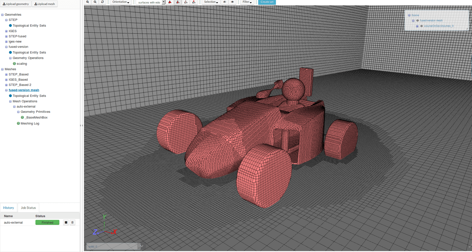
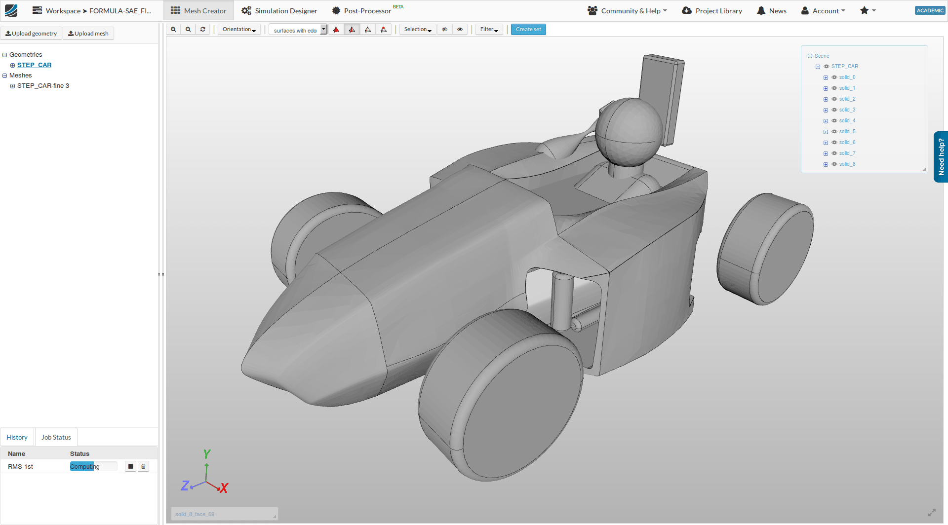
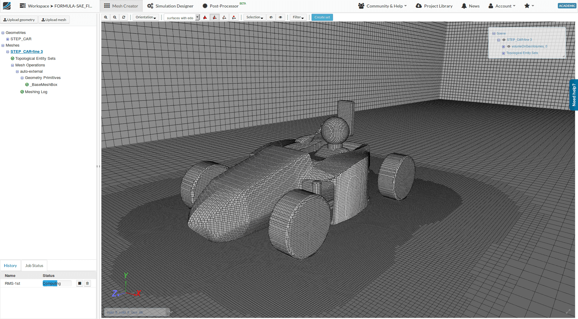
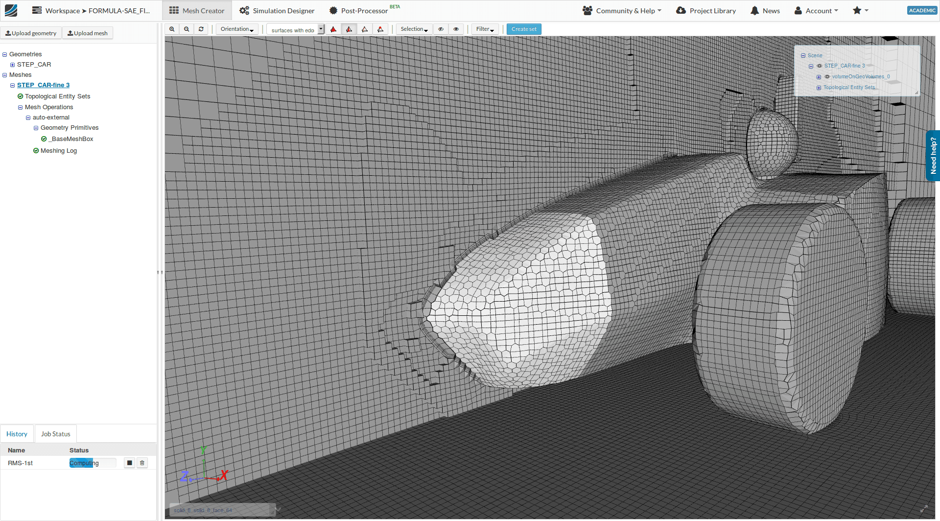
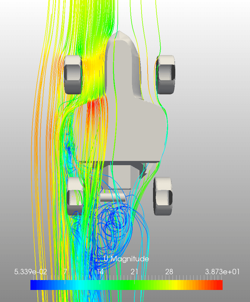
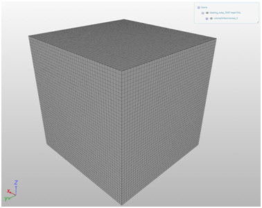
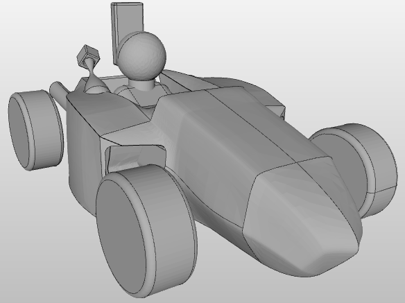
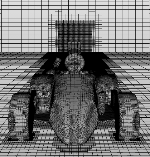
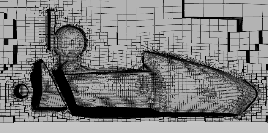
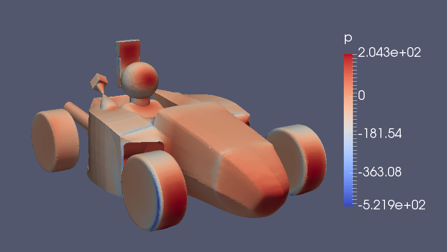
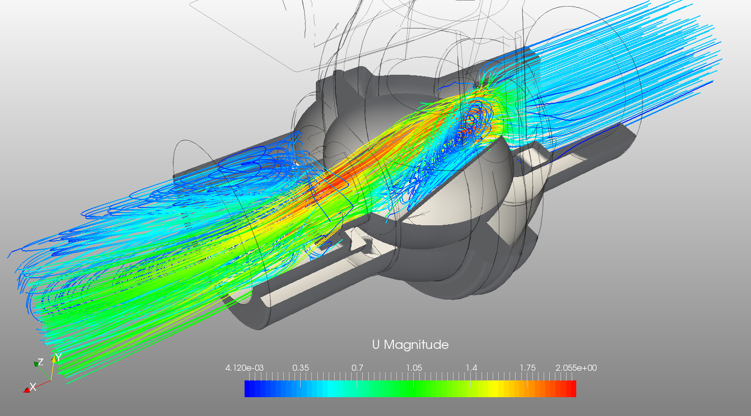
This becomes a problem at one step during the mesh generation, so the quickest way of fixing this would be fusing the solids that do overlap in such a way and uploading it again. So you could look if SolidWorks allows you to combine/fuse (a boolean operation) those solids. That way you would get rid of these overlapping/intersecting faces. I quickly fused them in my CAD system (another one) and exported it as an STL (which sometimes is easier to work with, but you do loose some capabilities, such as addressing a single face etc.). But then it worked (but the mesh could be a bit finer :wink: ):

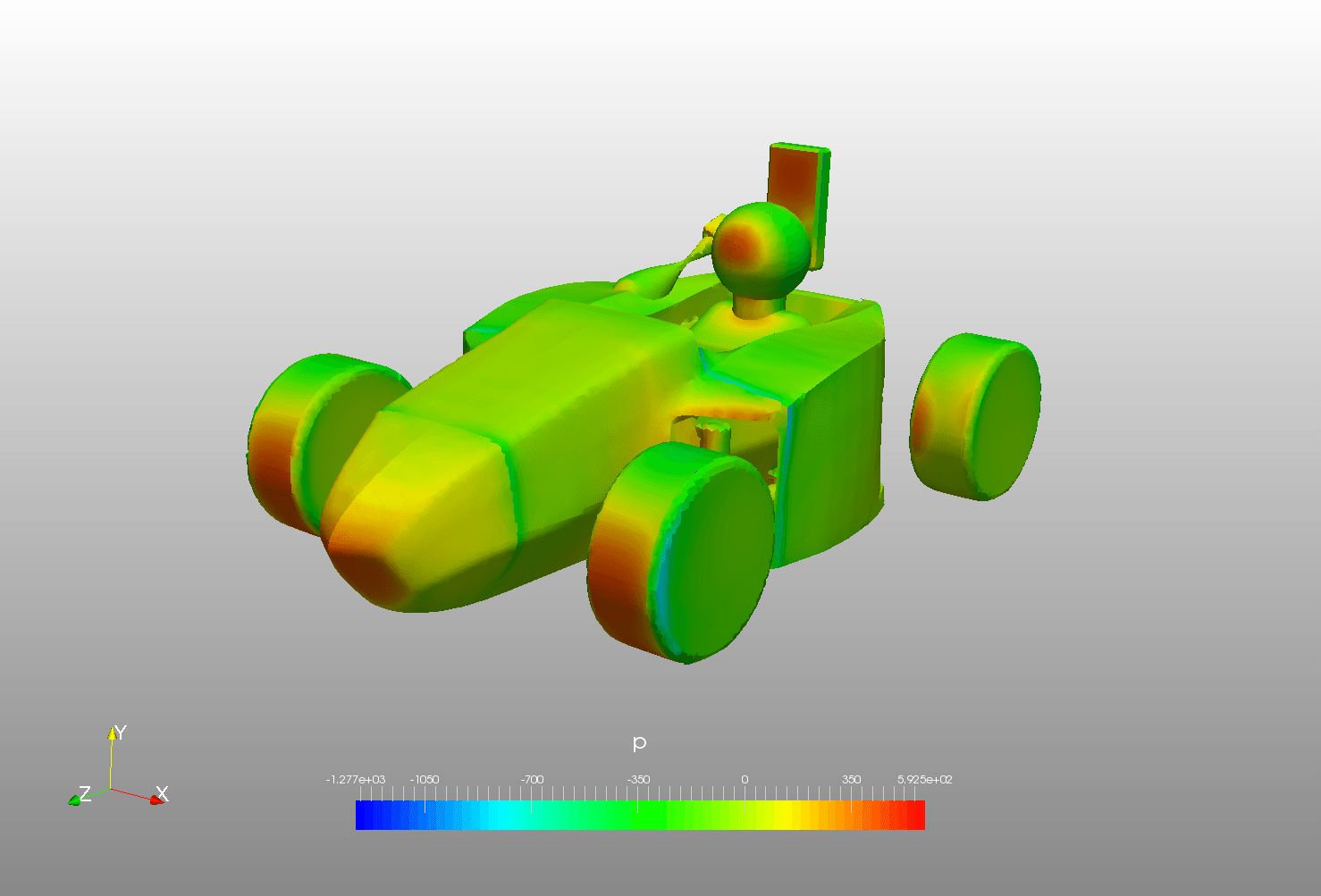
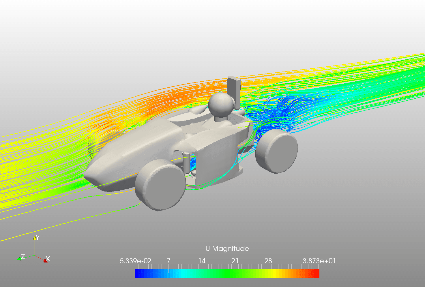
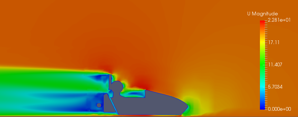
Did that help? Let me know if you have more questions. Looking forward to see the aerodynamic analysis of it :wink:

2 Likes

David,

fist of all, congratulations for your support, that was incredible. You were quick, effective and clear.

I understood the problem, I used the “cavity” feature of my CAD tool to cut the regions that were intersected by the car. That’s why there were overlapping regions in SimScale geometry. I did not know it was a problem for SimScale mesh generator.

I will fix it in the weekend, generate a proper mesh and put the feedback here. Thanks a lot!

Regards,

Lisandro

1 Like

Lisandro,

glad I could help!

So if I understand the “cavity” feature correct, that was a good idea. But after applying it fusing these parts should be the final step before uploading it to SimScale.

The detection and at some point also the healing of such properties in a CAD model is a current topic for the further development of the platform. So whenever you encounter such a situation, let the forum know about this. That way we can steer what kind of things the healing/cleanup should detect and potentially fix.

But now: Happy simulating ;)!

David

It’s great to see this kind of topics!

I’ve been on a Formula SAE Team and I faced that kind of problems and when I saw your question I knew the problem was the intersection of different solids (the same happened to me!) but I have seen that dheiny has solved it perfectly.

I hope you have great time on the different competitions! And I think it would be great if you tell us how your simulations advance.

1 Like

@lisandromaders,

thanks again for providing me with the project. Our CAD&Meshing team is constantly looking into how the CAD-to-Mesh workflow can be made more robust and reliable and they have multiple improvements and new features scheduled for this year. Yesterday we deployed an update of the CAD handling infrastructure that will also improve the robustness of the hex-dominant mesher. My colleague @arafat_ist therefore quickly tested it with your CAD model which seems to work nice:

Initial CAD:

Automatic hex-dominant mesh below. The mesh would need more attention (e.g. using the manual mesher, refining the wake region etc. - visible in the residual plots) but Ali was mainly interested how the geometry is handled by it and it worked smoothly.

Clipped view showing the refined layers:

Some very quick post-processing of some initial results - not really analyzed in detail. Pressure field:

Some streamlines:

More streamlines:

I just shared you the project for you to continue. It would be great if you share with us the progress!

Happy Simulating!

2 Likes

Hi @lisandromaders I’d like to add a few words to this discussion.

Well, for me such problems are nothing new and given my experience I would recommend:

1. Check geometry in your CAD program – I know, it’s obvious, but to be absolutely sure your model is clean do double check, which is:

  • create your geometry (whatever it is)
  • export it to .step file (or any other)
  • reimport it by your CAD system and check if everything is ok; what’s more, import assembly as a part file (!) as in CFD we need a coherent volumes without zero thicknesses
  • export again to the same file format
  • import to SimScale

2. Remember to place Material Point in sensible location.

3. Now setting mesh setup try to focus on features yourself – don’t leave everything to the program.

4. Further, try to use Surface Refinement instead of Edge Refinement. Why? Because Surface Refinement is focused on surface mapping while Edge Refinement refers to edges length.

I know it may sound funny (strange), rough or even patronising, but this is my way and it works (mostly :wink: ). Sometimes when you work with really complicated surfaces your CAD software may be unable to transfer sophisticated shape to different format. – It can even be unable to reimport properly what it exported (!). Bare it in mind.

In such situations your geometry imported to SimScale Mesh Creator may contain holes (cracks at the edges). It is still possible to mesh such geometry, but you have to increase toleration factor for mesher mapping. I can’t find such feature here, but the thing is you have to “tell” the mesher it should ignore elements (features, holes, cracks ets. everything) that is smaller than size you set. Therefore, if you use Edge Refinement (which I guess you set at the higher level than Surface Refinement) program will try to identify all edges that fit to this size (in practice really small / short edges) and will try to mesh them. And if the smallest (the shortest) edge for level refinement you set is shorter than the gap between two surfaces, than interior will be flooded. Below you have a very simple example:

INVALID GEOMETRY (box dimensions 100x100x100 [mm] | gap size 5 [mm])

PROPERLY DONE MESH - DOMAIN

PROPERLY DONE MESH – BOX

PROPERLY DONE MESH – CUT

IMPROPERLY DONE MESH – DOMAIN

IMPROPERLY DONE MESH – BOX

IMPROPERLY DONE MESH – CUT

Naturally both meshes based on the same input geometry.

2 Likes

@Maciek,

great - thanks for sharing! Indeed, the hex-dominant mesh operation is quite robust and “forgiving” even if the CAD model is not 100% well defined. Nice examples! I like especially this hint:

I’ve seen it quite some times, that a CAD model appeared to be fine in the native environment but once exported in a foreign format (e.g. stp) and imported again, one could see that some things were not well defined. Therefore +1 for this hint :smile:! As a side note: Support for more native CAD formats is being worked on to provide more options/flexibility when bringing CAD data into SimScale.

Hello David!

As I told you, I would give you the feedback of this simulation as soon as I finished some tasks I needed to do.

Just to introduce something amazing: this simulation was part of the RS Racing Formula SAE team, from Federal University of Rio Grande do Sul, Brazil, which reached the 2nd place in the National Formula SAE competition and conquered a vacancy in the International Formula SAE competition that will happen in June, 2016, at Lincoln, USA!!

Well, the simulation was quite simple in technical terms, and the objective was basically to predict the drag and down-force coefficients of the car. Here is some images of the presentation we did there:

1. Geometry was made in a CAD software


2. Some simplifications were made to reduce issues in mesh generation, like rounding motor,battery and cylinder surfaces.

3. Imported geometry into SimScale platform.

After having some issues which are related to this thread “CAD issues for CFD analysis”, everything was properly supported by SimScale team and the geometry was read fine.
4. Mesh generation

5.Results
The Cd obtained for 20m/s was 0.52, and car had lift instead of downforce of 0.16. That shown us the car need some improvement in its aerodynamics, since in Formula SAE competition having downforce is much more important than having a small drag value, once there is not too many straight sections and the velocity is not that high.

Below you can find some pictures (obs: I struggled to plot streamlines in ParaView, later if someone can give me some hints, I accept! :D)

6.Conclusions
For the scope of the team, that was a good simulation, since the values of coefficients we wanted to predict were not going to be use for nothing, only to know the aerodynamic behaviour of the car. The careen was already design and manufactured when the simulation was done. For the international competition we are planning to construct a whole new car. Therefore, much more care with mesh generation will need to be taken (I did not do any mesh independence study in this case). We are going to include a diffuser in the car as well changing the whole shape of it in order to reduce some recirculation we noticed with this simulations (close to the pilot).

So, giving you guys a feedback, I really liked to use the platform. I do not anything to complain, because when I did (creating this thread) I was perfectly assisted. I plan to keep using SimScale tools for the next Formula SAE simulations including FEM analysis (I only need to work around the core hours). If I do so, I will keep posting here feedbacks and doubts!

Thank you all that helped me! And feel free to like our Formula SAE facebook page: RS Racing Team

Regards,

Lisandro Maders

2 Likes

@lisandromaders Lisandro,

congratulations to you and your team on the 2nd place! Excellent!

The simulation also looks great (Find below a quick ‘How to’ for the streamlines in ParaView). Yes, it looks like there appears a recirculation area in front of the pilot head. Another question regarding the design: What’s the reason for the rather large surface behind the pilot’s head? Could this be reduced to further decrease drag?

Thanks for the feedback! It’s great to hear that SimScale is helpful in improving your car design! Agreed - solid mechanics and thermal analyses might be worth a look as well moving forward (I guess you might have seen the simulation workshop on F1 design). My colleague @Milad_Mafi takes care of our Academic Program (sent you his email address already) - he’ll be helpful in enabling your team to use SimScale moving forward!

Looking forward to more awesome simulation visualizations of your team’s car :smile:!

Best,

David

Quick Streamline How-to (I right now have an internal flow sim at hand - works the same for external):

  • Once you’ve imported the simulation result into ParaView, you do see the whole computational domain

  • Now apply the “Stream tracer” filter on this domain (I like to use the short cut Ctrl+Space, which opens a search window - simply type in “Stream” and the Stream tracer filter shows up - but you can also click the button in the top menu)

  • Before clicking the green “Apply” button of this filter, check on the “Seeds” settings of it. With these settings you basically choose “from where” stream lines should be computed. So you basically “seed” the streamlines with a couple of points in your domain. Most of the time I choose the “Point source” which means that you define one single point in your domain around which a number of points in a defined radius are being seeded. The “Radius” as well as the “Number of points” can also be chosen in this settings menu.

  • Paraview also previews where your point is (see the little white cross in the screenshot below). So you can either specify the location of the seed point via the coordinates in the menu or you drag and drop the white cross. In your case, ideally place it in front of your car.

  • Once you’re happy with the location, press the apply button

  • Depending on the flow pattern, you might want to use multiple point sources to have streamlines going through all interesting parts of the flow domain

Hii @dheiny can you please see my project because i am also facing the same issue. Some of the parts are not detected by the mesh creator .I have checked the geometry in the event log which is showing it is watertight but i do have shells.I uploaded the step file do i need to change the file format? I am ready to share the project with you.
Thanks in advance
Sachin Srivastava

Hi @sachin_srivast! Happy to take a look but it might take a few days

adding @sjesu_rajendra to the Conversation who might be able to help in the meantime

Thanks for tagging me in David!

Hi Sachin (@sachin_srivast),

I don’t see the project which has issues, in your public project library. Please share the project to support with a short reference to this forum post. We can check the issue and get back to you at the earliest possible.

Cheers,
Sam

hello @sjesu_rajendra thanks for the fast response, have to say your service is really appreciable.Here is the link of my project, https://www.simscale.com/workbench?publiclink=c4de492e-023e-4a4a-96e0-88832f7b8ad3 Sorry for the delay actually i encountered some other problems when tried generating mesh in STL format like now it is showing geometry is not water tight see if you can find the error in the geometry. I ll be very grateful to you. Have a look at this also in which was imported in STEP format https://www.simscale.com/workbench?publiclink=f970d286-0271-460e-87dd-5697ee35eaa1

Thanks

Sachin (@sachin_srivast),

Thanks for sharing the information. Ideally the STEP file is preferred for generating a mesh as the resolution of STL controls the mesh. I believe it is going to be external flow analysis, for which the current STEP file should be sufficient. Please use the Hex-dominant parametric mesh option with the material point placed outside the solid bodies, but within the limits of the bounding box (background mesh box). This way we can ensure that the mesh is generated in the right region. Also define mesh refinements appropriately to capture the geometric features properly.

Let us know if you have any other queries. Good luck!

Cheers,
Sam

Sam @sjesu_rajendra
I did what you said but its showing error in the execution of mesh operation. I have used 32 computing cores still it is saying machine ran out of memory. I have placed the material point outside the background mesh which i first made bigger than default one. I also added the mesh refinements . Please have a look on the project I hope you ll get it. https://www.simscale.com/workbench?publiclink=37e76aa6-d14a-4f4c-a79f-191376814207
Thanks

Hey Sachin (@sachin_srivast),

The refinements specified makes the mesh huge. It can be seen from the log that the process stopped at the point where the mesh exceeded 82 million cells :astonished: 
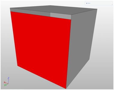
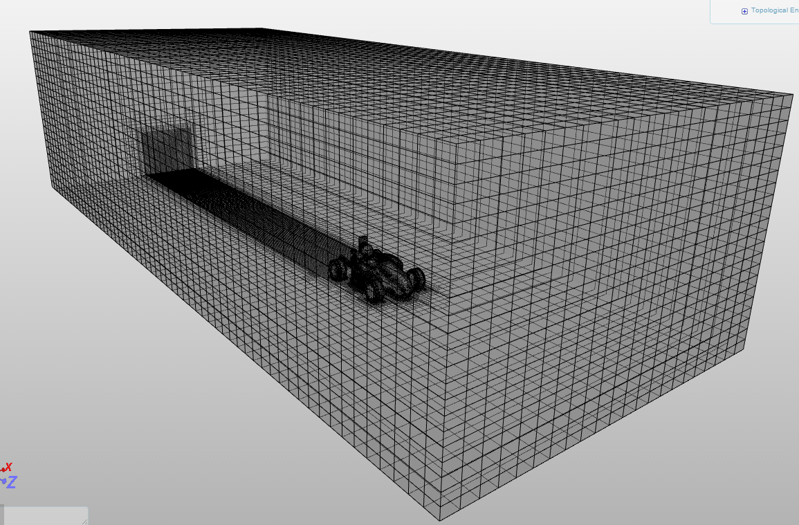
A hint would be to start with lower values and then proceed higher refinement levels depending on the requirement. May be a maximum level of 3 can be used, to start with!!

Sam

Hi Sam @sjesu_rajendra
Thanks for your constant support . I tried creating mesh with STL file with same refinement level i used with STEP one and guess what mesh got created but now i am facing different problem . I ran the simulation which had gone well for few hours after that it stopped saying the max run time is not sufficient adjust in the simulation control and create new simulation run. So i increased the max run time from 8000s to 18000s but after hitting start simulation button
I got the following message:
‘The maximum run time of this job would exceed your computation quota.You can try to adjust the settings under ‘Simulation Control’ and to create a new run.’
What is this?
Sachin

@sjesu_rajendra
The problem i mentioned above is solved thank You so much. Now the simulation is not running for full execution run time and event log also not displaying the reason for the error. please have a look at it . I am new to this online software, its pretty embarrassing asking question at each step i know.

see if you can help
Thanks
Regards
Sachin

Sachin @sachin_srivast,

Can you please explain the objective of this simulation? I see that there are no flow conditions (inlet/outlet) defined in the case. Please refer the similar project on Dolphin Hydrodynamics for defining such a simulation.

Best,
Sam