Hi there,
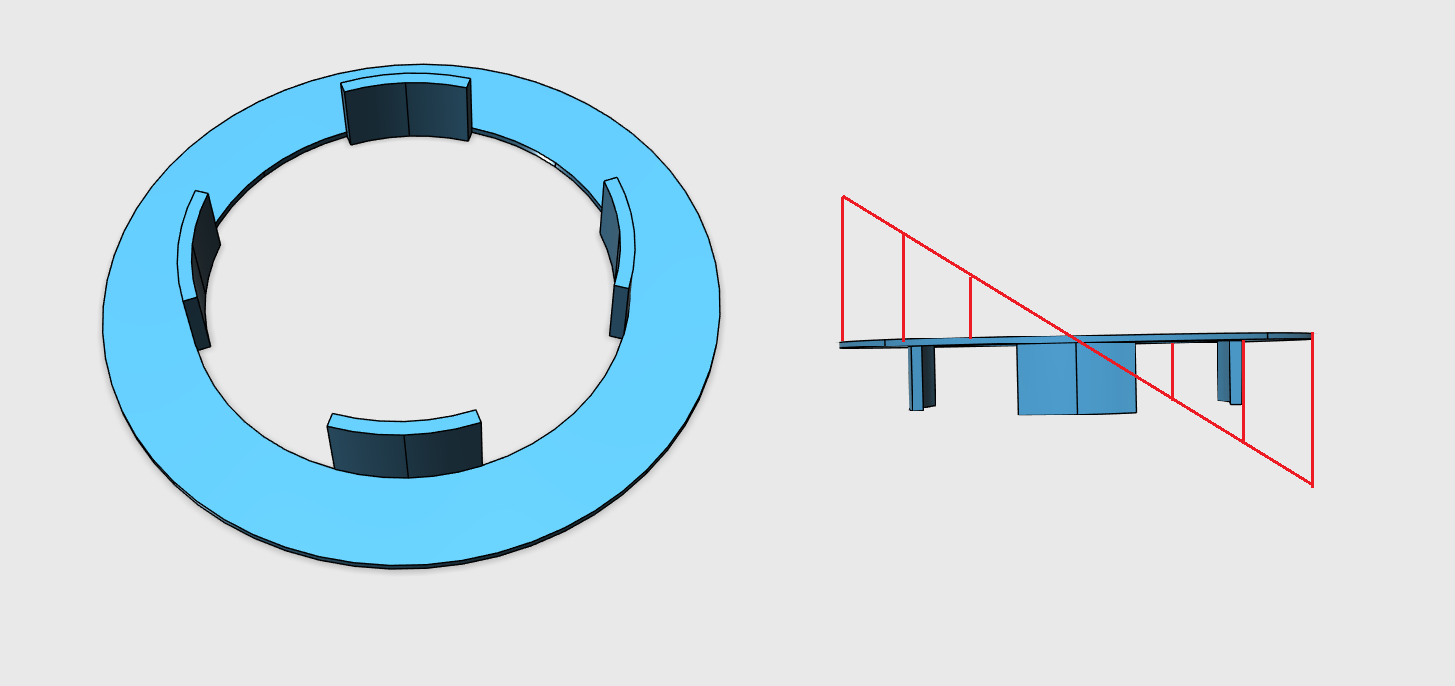
I want to apply a linearly changing, distributed load on a component “veergeleiding” (see pictures below). I want to apply the distributed load on the circular surface as shown at the left picture, which should vary linearly in a single direction (in my case this would be x-direction). Does anyone has a good suggestion how to model this? I’m aware I can create a function for a load/pressure distrubution but I’m not sure how I can make sure that the max/min values start/end at the outer sides of the circular surface?
I’ve already uploaded the model to SimScale:
Many thanks in advance!
Hi @jvarkevisser,
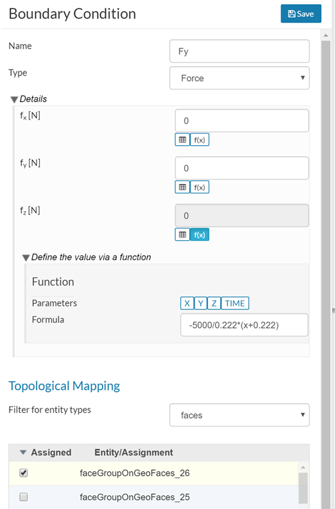
The formula you need is Fz = F_max / R * (X-X_0)
where:
F_max = max force at edge of circular plate (say 5000 N)
R = radius of circular plate (0.222 m)
X_0 = x distance from origin to center of circular plate (-0.222 m)
So, in this case, the formula would be Fz = 5000/0.222*(x+0.222)
Here is a link to a copy of your project with this formula.
Hope this helps.
Regards, Ben
5 Likes
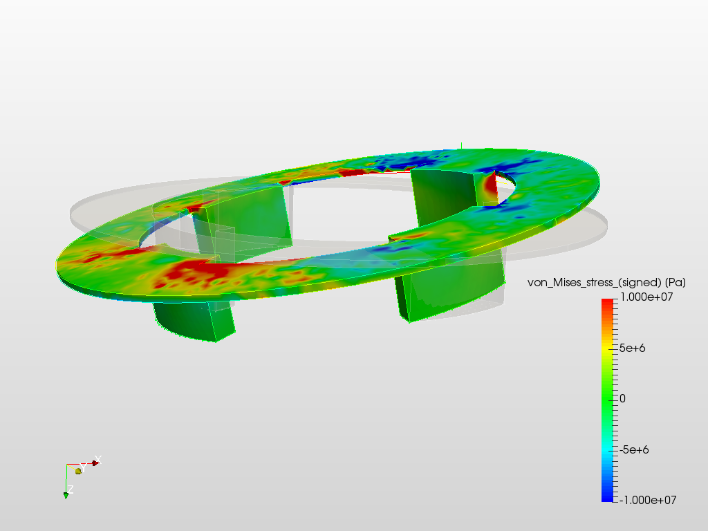
Hi @jvarkevisser,
Here is a screen shot of the results.
The patchy results indicate that the mesh is too course. It looks like your model would benefit form the use of a second order mesh.
Regards, Ben
5 Likes
Hi Ben,
Many thanks for the help! I will have a look at the results when changing the order of the mesh / refinement of the mesh.
Cheers