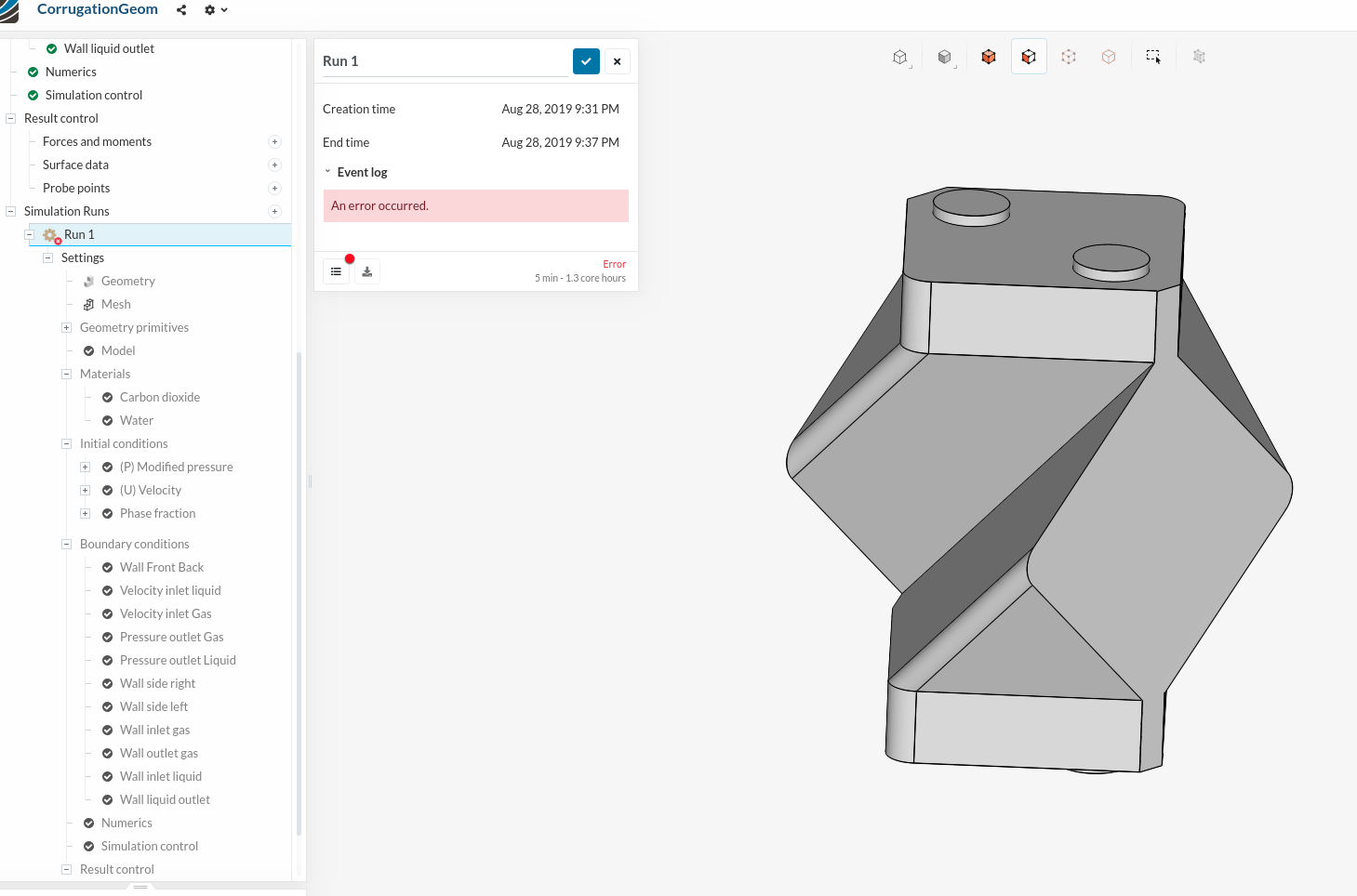
Is this joke? ‘‘An Error Occurred’’, that’s all I see, can’t find a detailed simulation log, nothing, nothing. How in the world of CFD I’m supposed to debug what’s wrong with my case just by reply from your “very very helpful” output?
I guess my simulations are failing just so that I can upgrade the plan, I see the marketing strategy of SimScale.
I can assure you that this is no joke. First of all it would be very helpful to have your project link so that we can have a look at your project in more detail. In addition to that you have the forum where you can ask your questions (in an optimal case without any rage and in a friendly manner) so that we can help you out
SimScale is continuously improving and we are working on it to make sure that messages like these become more specific in the future, especially with the wide variety of parameters that can cause an error (as previously mentioned)!
So please feel free to share your link here in the thread and we will help you out once we figured out the solution to your problem. Take it easy and happy SimScaling!
Few things that you have to take care of and I want to know from your side:
Not sure why you want to do local time-step but you already know what the value is?
The Mesh is large to run a multiphase sim on - we would suggest a parametric mesh
Most likely cause for the simulation to fail = Memory. Not sure if 16 cores is sufficient for this case - we can try running it with 32 and see if that solves the issue.
I have never tried a multi-phase simulation so I have copied yours and am trying to solve it for you. I have deleted all of the wall non-slip boundary conditions as simscale will places these automatically. Crucially, I have edited the phase fractions for your velocity inlets as currently both of your inlet phase fractions are 1 i.e. 100% CO2. You have no water entering!
You have set laminar flow instead of using a turbulent model despite your flow conditions being rather turbulent. I doubt this will cause an error message but it will cause very inaccurate results.
Your simulation time is for 1 second. I am not entirely sure that your model will reach steady state conditions within 1 second.
Did some runs on my own as well. Managed to get the simulation to run with your conditions but as Roy has mentioned there are no required results due to your inlet phase fractions.
The changes I made were to the time parameters. You will need to perform some rough calculations to determine what kind of timestep you are looking for so that you can set an optimal end time, but otherwise keeping adjustable timestep with a Courant of 0.5 should be fine for your needs.
You may also want to add a small radius round to the sharp edges of the internal geometery so the boundary layers can be better generated.
Likewise, what Jousef mentioned about 16 cores is correct. Stick with 32 since it is a transient simulation.
This occurs due to an instant error or instant divergence. While I agree it is not clear and the log isn’t present and could be improved, you’re getting this service for free and the least you can do is ask around first before flipping.
Unfortunately for all of us, paying money for a plan upgrade will still return the same error.
Hope you can see we’re all here to explore and help. We may not have all the answers and may not reply in an extremely timely manner but rather than expressing your frustrations with the platform, maybe a simple basic post would be a more productive course of action.
I didn’t know whether simscale applies the wall boundary conditions by default, hence as per the conventional openfoam way I decided to apply all sorts of boundary conditions. Thank you for that idea.
I still don’t know how to apply the phase fraction for one of the inlets, through which water is going to flow. If you can give that idea, that’ll be great. Essentially, what I did is created primitive cylinder geometry, then moved it near liquid inlet with co-ordinates manipulation, then at inlet to represent it as ‘block of water’ at initial condition.
But, I still got an error. Because, in conventional openfoam I know that I need to define bounding box in setFieldsDict which is located in system folder.
I did the Reynolds number calculations, considering the geometry as pipe, and for current velocity conditions, Re is less than 2600 which defines it as laminar flow.
About inlet Phase fraction:
I don’t know how to implement inlet phase fraction at the liquid inlet in simscale. Essentially, this can be done by applying bounding box in ‘setFieldsDict’ file in system folder of openfoam, as per the conventional way. I asked roy_g for input, as well as I would also like to hear from you about it.
About time step:
Yes, I kept adjustable time step along with Courant number of 0.5, but I was gonna start with 1E-5 just for the safer side.
About sharp edges:
I already changed the geometry and added the curvature on the corner for better boundary layer and reduce the turbulence. but further changes in geometry will defy the actual purpose of the geometry. Hence, I won’t be able to do that.
About 32 cores:
The first run that I did, it actually ran perfectly for 1 time step, until I saw Courant number at 256.000001, and after that it diverged. And I received detailed event log and solver log, I even learned from solver log that its running with ‘LTSinterFoam -parallel’. But later all ‘runs’ I only received ‘An error occurred’ and no detailed logs. So that’s the scenario where I wasn’t able to figure out what’s wrong with case, since all settings and pre-processing was showing ‘green tickmarks’.
Apart from that, I have another project in which this geometry is bigger with even more complex corrugation patterns. I ran that case on 16 cores with 5.2M cells for 11 time steps.
About Flipping:
I apologies for that, but I’m stuck in scenario where professor suddenly preponed the deadline while no results in hand. and no information for debugging apart from one single line message saying “an error occurred”
I can try parametric settings under meshing, but I don’t know whether it’ll generate the same type of results. Essentially, I wanted to have less cells in middle, and finer mesh on boundaries of geometry, because the results are based on critical factor of boundary layer and interstitial mass transfer rates between phases near boundaries.
Also, I wanted to know, can simscale perform reactions flows along with interfoam solver? In other words, can I modify the solver to add arrays of ‘scalarTransportVariables’, and perform the reactions of different species?
Well so far I get an error that the solution diverged. I suggest trying a simpler geometry until you get things working (like just a basic cube with two inlets and outlets) as it also didn’t mesh perfectly. As for setting phase fractions; notice in the material selection that you choose 1 material as phase 0 and the other as phase 1 and the following explanation is provided:
Phase 0 would mean this material is represented by the phase fraction value of 0. Hence, a phase fraction of ‘0’ in your setup corresponds to 100% of this fluid material.
Phase 1 would mean this material is represented by the phase fraction value of 1. Hence, a phase fraction of ‘1’ in your setup corresponds to 100% of this fluid material.
In the inlet conditions, under phase fraction, is a cell called value. Enter a value of 0 for 100% phase 0 and 1 for 100% phase 1 (or any number in between the two if you desire a mix of both phases)
In engineering we learn that curved edges are better than sharp edges, which is true for reducing stress concentrations, but in CFD/FEA you actually need a much finer mesh to mesh a small radius curve than a sharp edge so don’t assume that adding fillets will always make your model easier to mesh, it can often actually have the opposite effect.