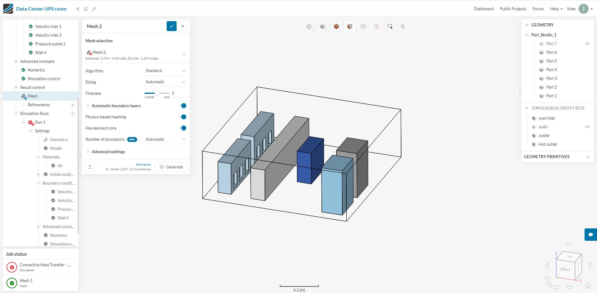
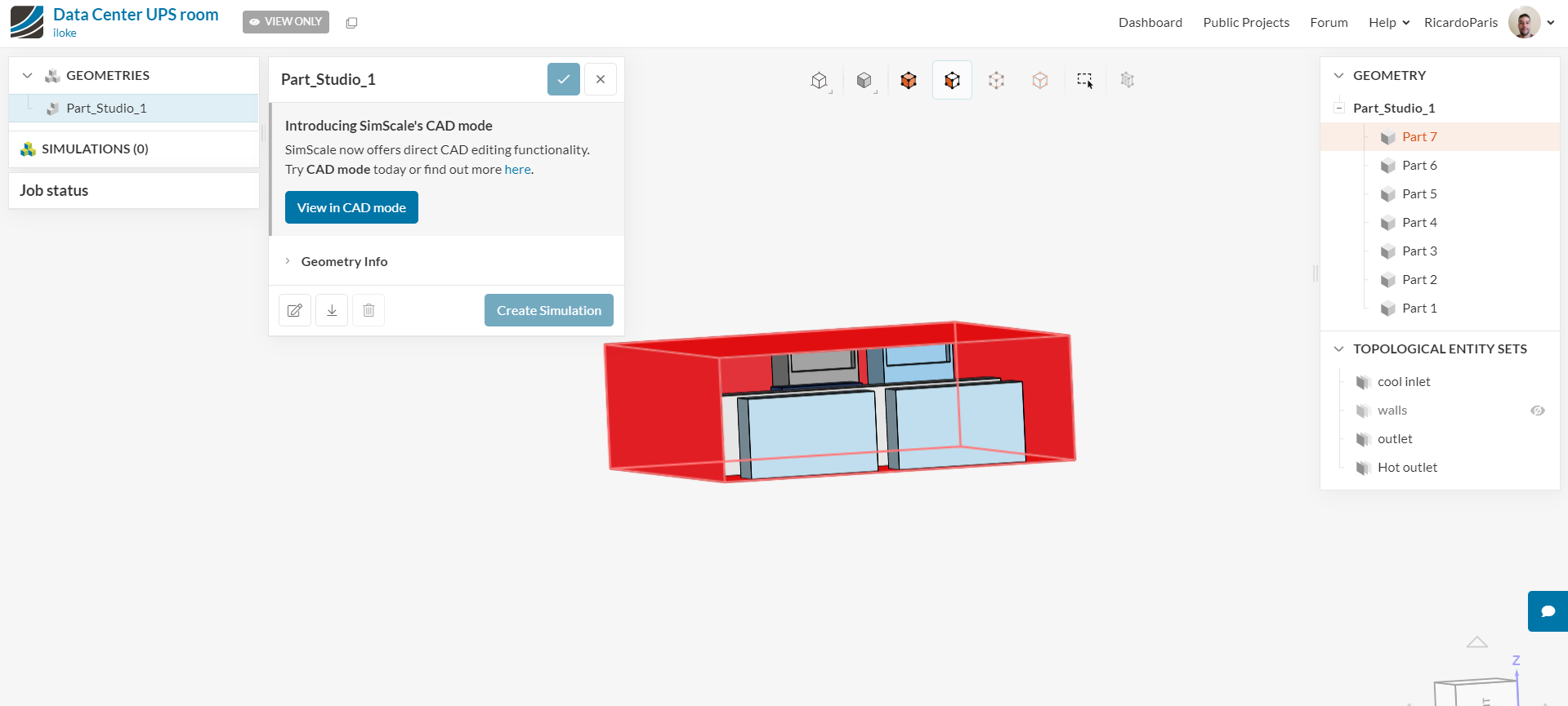
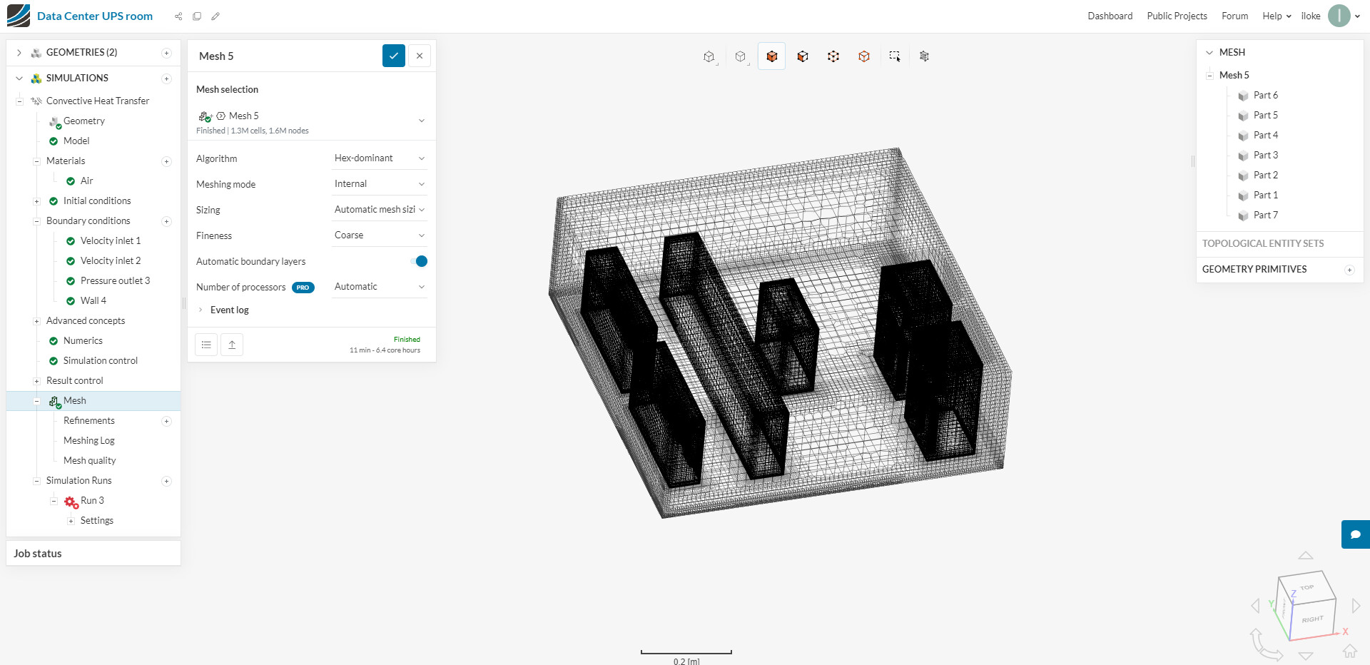
I did up a project which is based on the CFD simulation on cooling for a Data Center Uninterrupted Power Supply Room. I assigned a Meshing to the model, in the screenshot below the 2 tall blocks represent the Computer Air Handling Unit and the 2 long blocks with 3 holes in each at the back of the model are the UPS hot outlet where the hot air is suppose to come out.
I have deleted the solid bodies in the CAD edit mode to achieve this.
I left the other solids as they are part of the assigning of the velocity inlet & outlets under the boundary conditions.
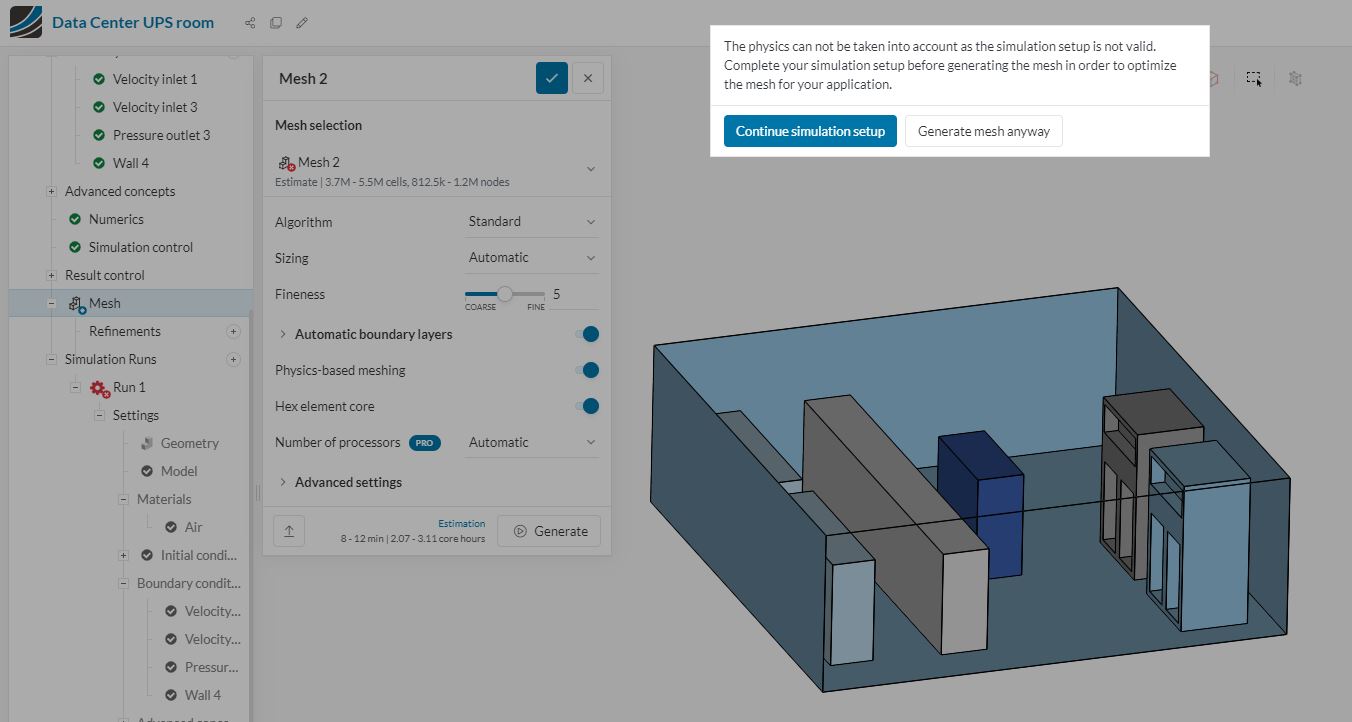
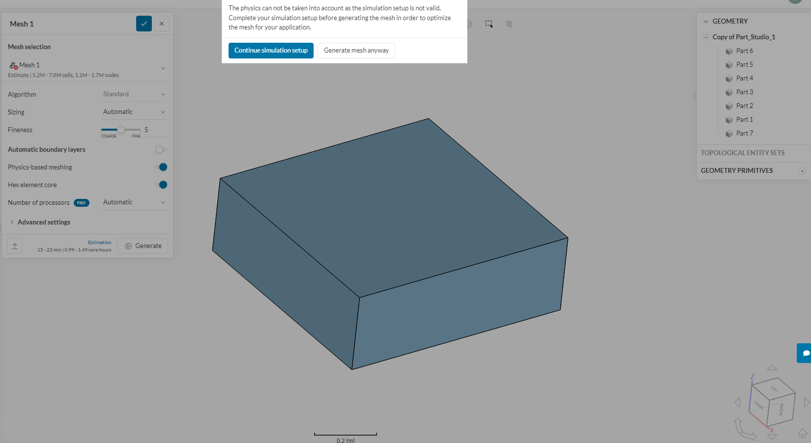
With regards to assigning the mesh I am still receiving the same error as illustrated in the photo below.
For the flow region it’s which area of the model? I’m not sure which flow region you’re referring to. Basically I have to delete the walls which are the solids and can leave the components in the CAD edit? I So for boundary conditions I only select on area which is the floor which is in contact with the solids?
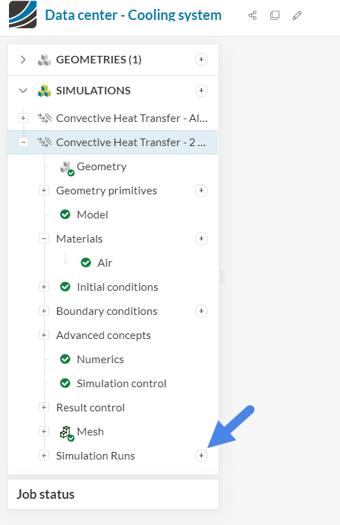
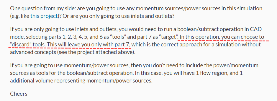
One question from my side: are you going to use any momentum sources/power sources in this simulation (e.g. like this project)? Or are you only going to use inlets and outlets?
If you are only going to use inlets and outlets, you would need to run a boolean/subtract operation in CAD mode, selecting parts 1, 2, 3, 4, 5, and 6 as “tools” and part 7 as “target”. In this operation, you can choose to “discard” tools. This will leave you only with part 7, which is the correct approach for a simulation without advanced concepts (see the project attached above).
If you are going to use momentum/power sources, then you don’t need to include the power/momentum sources as tools for the boolean/subtract operation. In this case, you will have 1 flow region, and 1 additional volume representing momentum/power sources.
In my simulation. I am only assigning inlets and outlets to the project. I will have to keep parts 1 to 6 as tools. The internal volume of part 7 will be where the simulation of the airflow and temperature takes place. Previously, I had assigned my velocity inlets for part 1 & 2 for being the CRAC units, Velocity inlet for being the hot inlet for part 5 & 6 , pressure outlets for being part 1 & 2 and in your picture that you highlighted as red are the walls for the boundary conditions. The other parts are circuit breaker components in the room which are needed to be kept there for the simulation.
When assigning the internal volume in CAD edit mode, which are the parts to select as the seed face and subsequently for the boundary faces?
For the meshing part, I will select the part 7 to be the only part of the meshing process? Unable to generate mesh because of this error.
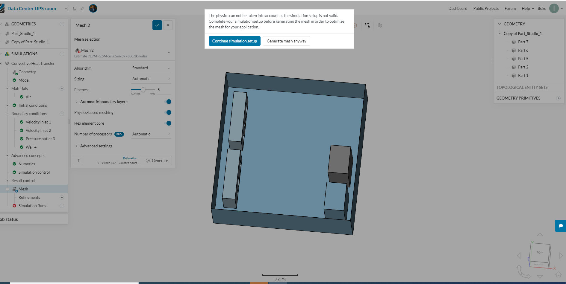
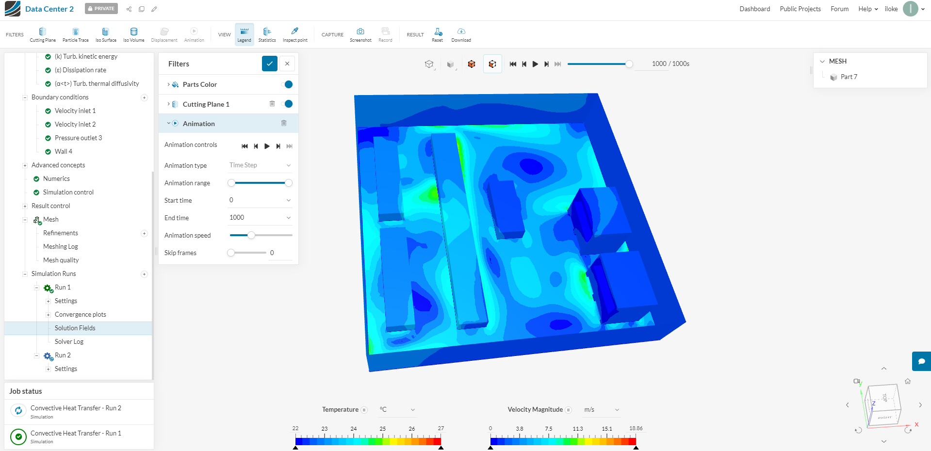
If you follow the boolean/subtract steps that I mentioned in my previous response, you will end up with a flow region containing the negative representation of the solids.
The boundary conditions will be applied directly on the flow region, using the “negative representation” of the solids for the assignment (again, the description of this public project shows how it looks).
Now, I tried to find the faulty simulation in your projects, but it seems to have been deleted. So unfortunately there is not much input that I can give here. If you do run into this issue again, I would recommend trying to run a simulation directly. A window will show up, showing which parts of the setup are invalid.
So once I subtract I do not have to have to assign the internal volume? More of the issue comes from the meshing. Once I do the simulation runs I’ll post it here again! Thanks
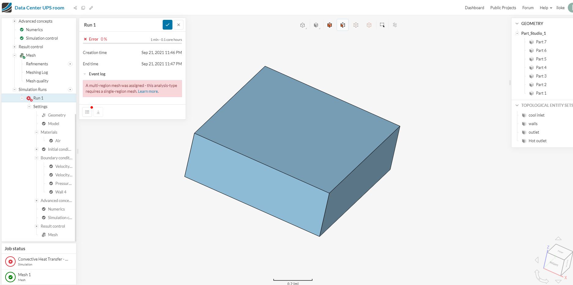
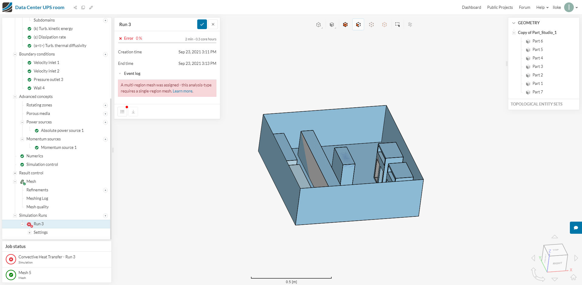
I have used the boolean/subtract command as you stated above. Then, I have carried out meshing and simulation for the above project. However, there’s an error which states: “A multi-region mesh was assigned - this analysis-type requires a single-region mesh.”