Documentation
This bonded contact gravitational load validation case belongs to solid mechanics. This test case aims to validate the following parameter:
The simulation results of SimScale were compared to the analytical results derived from [Roark]\(^1\).
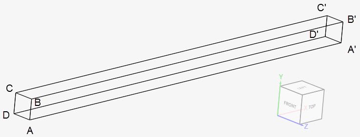
Two beam geometries are used for this gravitational load validation. They have a cross-section of 0.05 x 0.05 \(m^2\) and 1 \(m\) length (l). The first one consists of unrotated beam geometry, shown below:
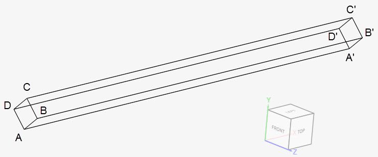
The second geometry is rotated 45º around the positive x-axis:
The coordinates for the points in the first geometry are as tabulated below:
| A | B | C | D | A’ | B’ | C’ | D’ | |
| x | 0 | 0 | 0 | 0 | 1 | 1 | 1 | 1 |
| y | 0 | 0.05 | 0.05 | 0 | 0 | 0.05 | 0.05 | 0 |
| z | 0.05 | 0.05 | 0 | 0 | 0.05 | 0.05 | 0 | 0 |
Similarly, for the rotated geometry, we have:
| A | B | C | D | A’ | B’ | C’ | D’ | |
| x | 0 | 0 | 0 | 0 | 1 | 1 | 1 | 1 |
| y | -0.03536 | 0 | 0.03536 | 0 | -0.03536 | 0 | 0.03536 | 0 |
| z | 0.03536 | 0.0707 | 0.03536 | 0 | 0.03536 | 0.0707 | 0.03536 | 0 |
Tool Type: Code Aster
Analysis Type: Linear static
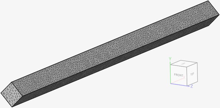
Mesh and Element Types: The meshes for cases A and B were created in SimScale. The standard algorithm was used. The meshes from case A and B were downloaded, rotated by 45º around the positive x-axis, and imported to SimScale. They were used for cases C and D, respectively. With this method, we achieve the same meshes for the rotated and unrotated cases.
| Case | Geometry | Mesh Type | Number of Nodes | Element Type |
| (A) | Beam – original | Standard – tetrahedral cells | 12737 | 1st order |
| (B) | Beam – original | Standard – tetrahedral cells | 91499 | 2nd order |
| (C) | Beam – rotated | Standard – tetrahedral cells | 12737 | 1st order |
| (D) | Beam – rotated | Standard – tetrahedral cells | 91499 | 2nd order |
Find below the mesh used for case D. It’s a standard mesh with second-order tetrahedral cells.
Material:
Boundary Conditions:
Converting the gravitational load to a line load \((w_a)\):
$$w_{a}l = V.\rho.g \tag {1}$$
Solving \((1)\), we have:
$$w_{a}=193.01175\ N/m \tag {2}$$
The moment of inertia \(I\) is given by:
$$I = \frac {b.h^3}{12} = 5.20833⋅10^{−7}\ m^4 \tag {3}$$
The equation (4) below is derived from [Roark]\(^1\)
$$y(l) = -\frac{w_a l^4}{8 E I} = -2.2597 \cdot 10^{-4}\ m \tag {4}$$
The table below shows the SimScale results for the displacement at the free end (face A’B’C’D’) in the gravity direction. Results are compared to the analytical solution by [Roark].
| Case | Quantity | [Roark] | SimScale | Error (%) |
| (A) | Displacement at the free end \([m]\) | -2.2597e-4 | -2.1480e-4 | -5.20 |
| (B) | Displacement at the free end \([m]\) | -2.2597e-4 | -2.2560e-4 | -0.16 |
| (C) | Displacement at the free end \([m]\) | -2.2597e-4 | -2.1480e-4 | -5.20 |
| (D) | Displacement at the free end \([m]\) | -2.2597e-4 | -2.2560e-4 | -0.16 |
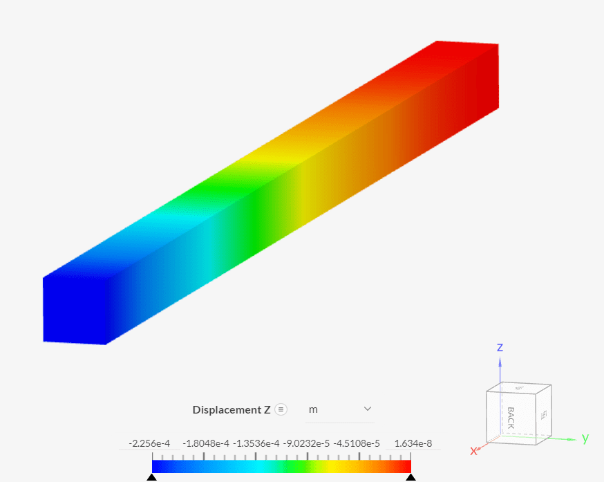
Inspecting the displacements in the z-direction for case B:
References
Last updated: November 7th, 2023
We appreciate and value your feedback.
Sign up for SimScale
and start simulating now