Thermal management plays a crucial role in the design of electronics equipment as it directly affects reliability and might cause untimely failure of the product. Consequently, a need arises for engineers and designers to thoroughly investigate multiple design scenarios that would result in an efficient cooling strategy. Access to numerical simulations at an early design stage can reduce the cost of physical prototyping, and most importantly, increase confidence in the overall product quality. SimScale offers an engineering simulation solution for simulating radiation heat transfer that allows for automated parallel computation, full exploration of multiple design iterations, reduced costs and time investment in the prototyping phase, and in-platform CAD editing for a streamlined simulation workflow. This article explores a case study on thermal radiation and an overview of radiation effects that should be included in engineering simulation studies.
Case Study: Enclosed LED Heatsink
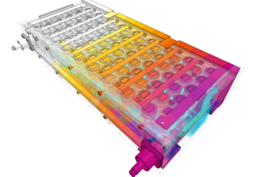
The electronic device in question is an enclosed LED heatsink with a metal core PCB as shown below.

Using the Conjugate Heat Transfer (CHT) simulation type in SimScale a full thermal analysis was performed with a focus on radiative heat loss contribution.
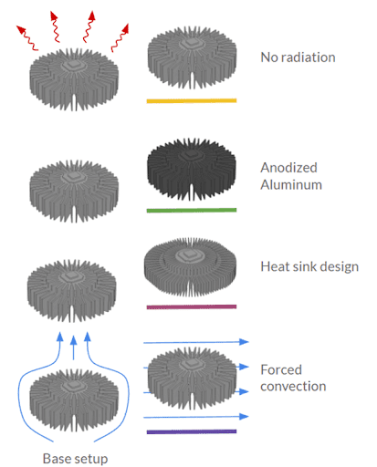
In order to better understand the influence of radiation on the proposed LED heat sink, multiple design considerations were investigated:
- Radiation: Disabled vs Enabled – To understand if we should consider radiation in further design iterations
- Surface finish: Anodized aluminum vs radiative paint – To understand the influence of increasing the emissivity of the heat sink surfaces
- Heat sink design: ‘Dense’ vs ‘Sparse’ heat sink – To understand the influence of increasing the total surface area of the heat sink on the overall heat transfer.
- Cooling strategy: Natural vs forced convection – To understand the overall contribution of radiation in both cooling scenarios.
The comparisons were done by varying one parameter at a time as illustrated in the figure below.
Simulation Setup
- A steady-state Conjugate Heat Transfer (CHTv2) simulation is used to model convection, conduction, and radiation
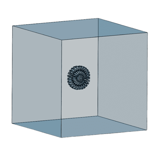
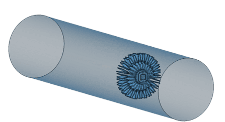
- The flow volume that encloses the LED CAD module can be created using our CAD mode feature, which is used to create two flow regions as follows:
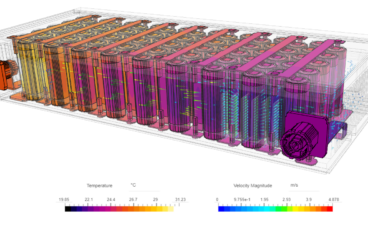
- Box: To emulate the setting of a natural convection scenario where the device sits open to the environment. The flow is allowed to enter and exit freely through the boundaries of the box.
- Cylinder: To emulate the effect of a forced convection flow. Where a flow rate of 0.04887 m3/s was applied to the inlet face.
- The materials used:
- PCB: Aluminum (emissivity = 0.3)
- LED chip: Silicon (emissivity = 0.9)
- Heat sink: Anodized Aluminum (emissivity = 0.7)
- Aluminum with radiative paint (emissivity = 0.95)
- The ambient temperature is 19.85 °C
- The total power dissipated by the LED chip equals 10 W.
- The standard mesher with automatic settings was used.
- The average time to complete one of the particular design iterations mentioned above is between two to three hours. However, because SimScale allows all simulations to be run in parallel with cloud computing, this now becomes the total time needed to run all design scenarios.
Simulation Results
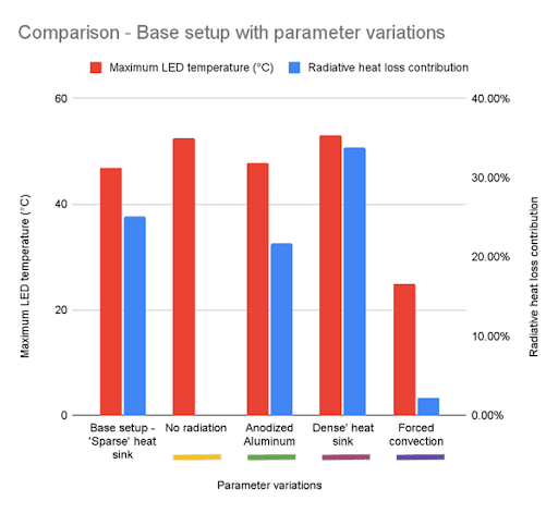
The chart below compares the results obtained from the base setup with its design variations.
- The left axis provides the maximum LED temperature in °C.
- The right axis provides the contribution of radiation to the overall heat loss in the system.
- The bottom axis shows the design variations simulated.
Radiation Enabled vs Disabled
The first design variant stems from asking, “Do I need to include thermal radiation effects in my further design iterations?”
The answer is yes. If we compare the results obtained from the base setup with the results from the simulation without radiation, we can clearly see that the maximum LED temperature obtained with radiation activated was around 46 °C while in the case without radiation was 53 °C. That’s about 27% increase in temperature when radiation effects were not included in the base design, and a sufficient indication that thermal radiation effects should be considered. Moreover, it can be seen that in the base setup radiation contributed close to 30% of the total heat loss in the system.
Surface Finish: Anodized vs Radiative Paint
Using Anodized Aluminum as a material for the heat sink contributed to lower radiative heat loss when compared to its radiative paint finish counterpart. Subsequently, this resulted in a higher LED temperature with a value of around 47 °C.
Heatsink Design: ‘Dense’ vs ‘Sparse’ Heatsink Fins
Interestingly, the maximum LED temperature obtained for the design with a dense heat sink proved to be higher than the design with a sparse heat sink; 53 °C in comparison to the 46 °C of the base setup. This is simply due to the low velocities that are usually encountered in natural convection which results in insufficient flow penetrating the gaps between the fins and hence not providing adequate cooling.
On the other hand, the radiative heat loss contribution was almost 5% higher than in the base design.
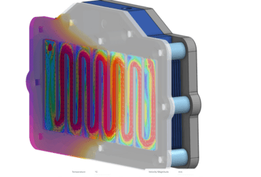
Cooling Strategy: Natural vs Forced Convection
In the forced convection case the maximum LED temperature recorded was significantly lower than the other design variants with a natural convection cooling strategy. In this case, 25 °C in comparison to 46 °C with natural convection. Moreover, the contribution of radiation to the overall heat loss is about 2% which is minimal.
Simulating Radiation Heat Transfer for Optimized Thermal Management
Designers have opportunities at an early design stage to optimize the performance of electronic products by investigating multiple factors like thermal management, materials, geometries, and environmental conditions. With thermal management playing such an important role in electronics design it is crucial to investigate the contribution of the three fundamental heat transfer methods to the overall heat loss of the system and it is especially important to consider radiation heat transfer effects. Using CFD thermal simulation numerically replicates working conditions, materials, and heat thermal transfer methods on a 3D model so that the design engineers can make informed decisions.
This on-demand webinar introduces our radiation heat transfer simulation features for electronics cooling. Watch and learn how to efficiently mesh the model, set up the boundary conditions including gravity, enable radiation, and post-process and visualize the simulation results: