The accurate simulation of turbomachinery, pumps, and propellers is traditionally viewed as a non-trivial process, reserved for highly experienced computational fluid dynamics (CFD) analysts that represent a significant investment of time and resources for a company. The outcome that I often see is that many companies rely on physical prototyping for design iterations. Nine times out of ten results in sub-optimal products and significantly delayed product releases. This “simulation accessibility” problem stems from the complexity of traditional CFD tools (baffling UI’s with steep learning curves) combined with the high cost of software ownership. SimScale’s cloud-native simulation platform provides an intuitive CFD solution for turbomachinery designers and engineers directly in your browser, with no software or licensing to install, in-product live chat support, integrated tutorials, and documentation that provide an eminently more accessible simulation solution. We have recently added several exciting new features to our proprietary CFD technology, including automatic mesh refinement, enhancing the user’s simulation workflow experience, improving results accuracy, and speeding up solution times. These build on the recently released transient analysis capability and demonstrate Simscale’s commitment to this industry segment.
Automated Mesh Refinement
A robust, automated body-fitted mesher with local refinement has been specifically developed for turbomachinery/pump applications. This new capability consists of two related features: An improved automated global mesher and the semi-automated local refinement feature. Together they provide users with more granular mesh control around areas of interest such as rotor/impeller blades, rotor wake, or any small features that could be important to factor into a simulation.
The resultant body-fitted meshes are highly optimized and yield accurate results whilst considerably reducing the numerical problem size. Thus yielding proportionally faster solution times and consumption of fewer CPU core hours boosting an engineer’s productivity. Here are some examples:
Automated Global Mesher
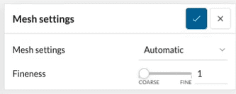
The new global mesher is very robust and able to handle complex CAD geometry with minimal cleanup. When Automatic Mesh settings are chosen, a Fineness slide bar is available allowing a value between 1 to 10 to be set as shown below:
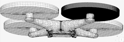
Below is an example of the new mesher applied to a drone/UAV quadcopter, where the new global mesher achieved approximately a 50% reduction in mesh size (number of cells) with the same accuracy, and a 20-30% reduction in solver runtime.
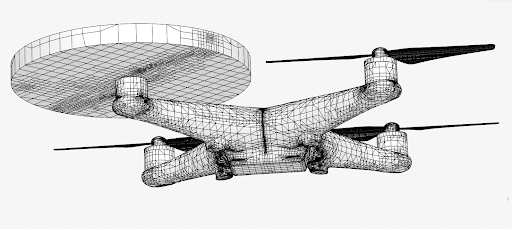
Top: The old global mesher is shown with no local refinement.
Bottom: The new global mesher output with local refinement around one of the four rotors.
Local Mesh Refinement
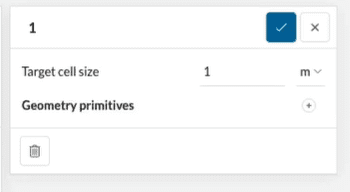
This feature allows a user to specify a target cell (element) size for the model contained within a defined geometry primitive (either a cylinder or cartesian box), and as such enables both fine or coarser mesh regions to be defined.
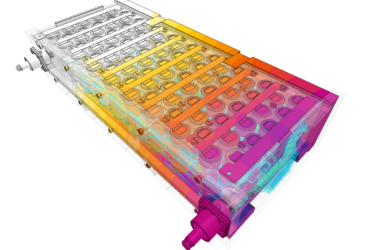
The mesh coarsening approach can be effectively used to reduce the numerical problem size (the number of cells/elements) substantially by defining a relatively coarse mesh in less important regions of the model such as in the upstream or downstream far field. Any number of refinement regions can be defined with independent degrees of refinement, plus this feature can also be used in conjunction with SimScale’s automatic global mesher that acts on the entire model for further control over the meshing. Here’s an example of the local mesh refinement applied to the impeller region of an axial centrifugal compressor:
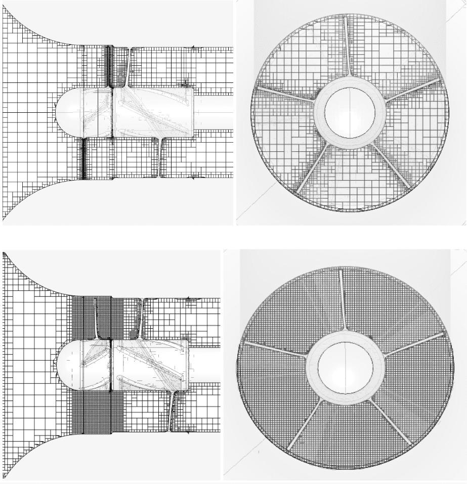
Top: Shows just the global automated mesher results.
Bottom: Shows the results of local mesh refinement around the impeller and compressor blades.
Right: Detail view along the axis of the compressor showing very fine mesh refinement around the blades & wall of the inlet.
Workflow Enhancements
We’ve also released several workflow enhancements to help users accelerate parametric design iterations and save time when setting up their simulations.
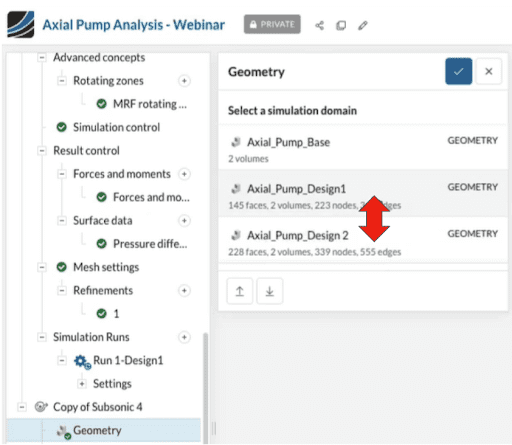
Onshape® CAD Associativity
A very common workflow is to swap geometries being simulated in a project to compare the performance of similar variants. In such cases, with most simulation tools, the user will have to re-assign all of the loads and boundary conditions to the geometry, and this can take a significant amount of time. This new feature automates the assignments and/or retains as many assignments as possible between similar geometries when using geometry from Onshape®. This makes it very easy to run simulations with multiple versions of a part or assembly, and can even be automated through the use of the Simscale API. Note that this is a distinct feature from parametric geometric variation where one or more dimensions are varied per simulation.
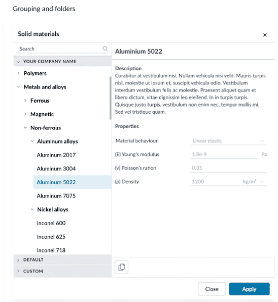
Personal Material Library
While commonly used materials like steel, iron, aluminum, etc are provided in the default material library, users are able to create custom materials within a project. The new Personal Material Library extends this functionality by allowing users to create their very own Materials Library that can be shared across projects.
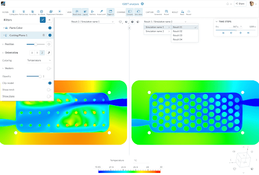
Visual Result Comparison
Users can investigate two models side-by-side, matching field result viewing angles, cut plans, contours, and legends allowing for a direct comparison. This feature is valuable in highlighting differences (or similarities) in results, especially when simulating variations of the same design. The two side-by-side comparison views can also be decoupled, allowing independent exploration of each model. This can be very useful when generating images for reports/presentations, for example when an engineer needs to maintain global context while showing a zoomed-in or rotated view at the same time.
Cloud-Native Simulation for Turbomachinery Applications
SimScale is committed to making fast and accurate simulation accessible to designers and engineers involved with developing turbomachinery, pumps, and propellers enabling simulation adoption throughout the product’s lifecycle. Our proprietary simulation technology is already helping companies in this industry realize significant product research, development and manufacturing costs, and resource savings, which in turn allows them to bring better, innovative products to market faster.
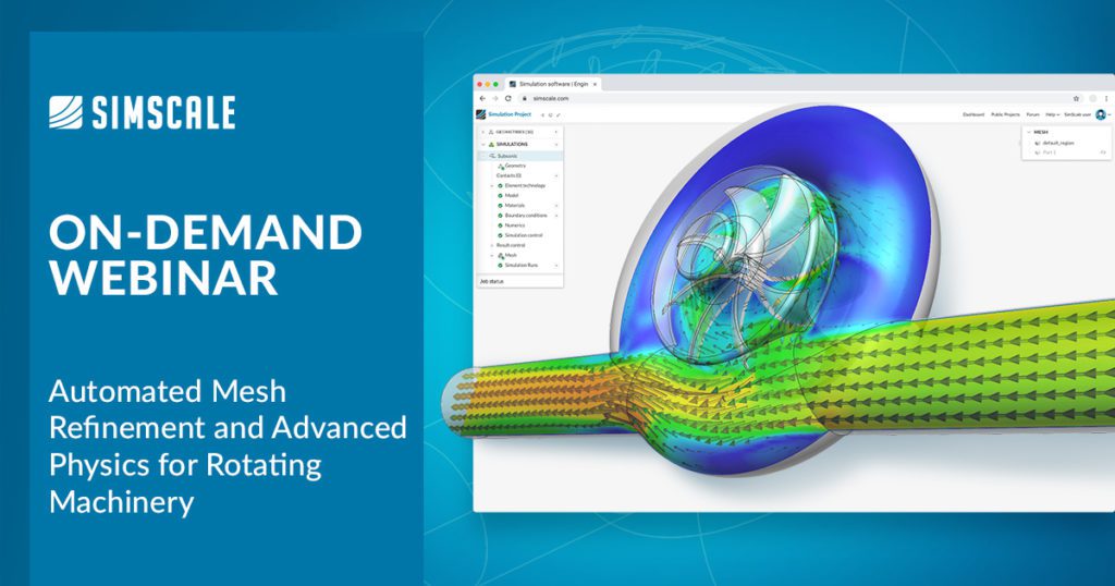
Learn even more in our on-demand webinar, Automated Mesh Refinement and Advanced Physics for Rotating Machinery. See how local mesh refinement can be used to create high-quality meshes for rotating machinery applications while optimizing simulation turnaround time and core-hour utilization: