When engineers think of computational fluid dynamics (CFD), some typical use cases that spring to mind are internal flow (e.g., piping) or external flow (e.g., aircraft aerodynamics). However, an area that has gained a significant increase in CFD usage is computational wind engineering (CWE), or wind engineering, due to the complexities involved and the ever-increasing availability of computational power. From wind comfort assessment to air exchange effectiveness and structural loading due to wind effects, such studies are normally done in expensive wind tunnels and rarely online. Furthermore, these practical studies are only done for very special cases and even so, in a limited capacity. Today, due to the aforementioned increase in the availability of cheap substantial computing power, more of such studies can be worked on for additional cases.
This comprehensive article in particular deals with incompressible external flow of urban environments and is a beginner’s guide for performing this type of wind engineering simulation. Some aspects outlined in this post can be used for other types of CWE simulations as well, but the methods listed may not be optimal for all types of wind simulation.
Wind Engineering Important Considerations Before Starting a Computational Wind Engineering Simulation
The end goal of a wind simulation is the first thing one should consider, and layout, before embarking on the task. For incompressible external flow, is wind comfort of a particular area to be analyzed? Deduction of peak wind loads on specific structures? Cross-ventilation in order to determine the ventilation performance for the internals of a building? The establishment of what exactly needs to be analyzed is the first step towards ensuring that the wind engineering project can be done as efficiently as possible.
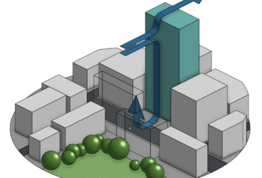
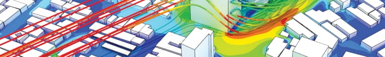
For example, if you were planning to determine the pedestrian wind comfort in a simple urban environment with no change in ground elevation as seen in Figure 1, there would be no need to model the internal layout of the geometry even if it was available. The inclusion of the internals would not only not affect the final result, but would unnecessarily increase the computational cost due to the extra internal mesh needs.
Of course, if ventilation needs to also be analyzed, then the internals will need to be included and meshed. Yet, now the surrounding geometry loses importance as the inclusion of which would not adversely affect the results internally. A question then arises; when should details of the geometry (internal or external) be included and how detailed do they need to be?
Wind Engineering Spatial Scales
Spatial scales are the next important consideration to help determine what should or should not be modelled. Incorrect selection or non-inclusion of the correct spatial scale will result in simulations that may not be able to sufficiently represent the actual built environment. Shown in Figure 2 are the different types of spatial scales.
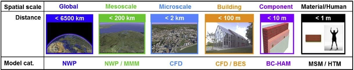
In an ideal world, one would be able to include all spatial scales for the simulation in order to replicate the real environment as closely as possible. Obviously, this is not only impossible but also extremely inefficient. As such, well-made assumptions must be used. Typically, environments in the micro environment and building scale are modelled and simulated with assumptions to the inputs into that environment. In the case of the microscale, the average wind speed from a specific direction would be assumed, while for the building scale, a simple velocity inlet at an opening with the wind velocity at that height would often be sufficient.
The usage of different spatial scales in one geometry only arises when the area of interest starts becoming increasingly complex. Say that the internal ventilation characteristics of a building need to be considered, but the building lies in the midst of large irregular structures. In this case, simply assuming an inlet velocity may not be sufficiently representative, and thus the microscale will also need to be modelled. In addition, this has the potential to increase the computational cost significantly.
Learn how to leverage the SimScale cloud-based simulation platform to optimize your design based on accurate results and ensure pedestrian wind comfort and safety!
Wind Engineering Wind Engineering Software and Hardware Considerations
Software and hardware considerations are of particular importance for wind engineering and CWE simulations. Due to the large scales and subsequently large complex meshes involved, particular attention needs to be paid towards the availability of computing power. Often, simulations are completed scaled down, therefore compensation needs to be made to ensure the effects are still properly represented at a reduced scale. Inherit software and hardware costs involved to perform computational wind engineering analyses can be costly and will inadvertently limit what cases can be simulated.
Wind Engineering CWE Simulation with SimScale
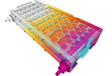
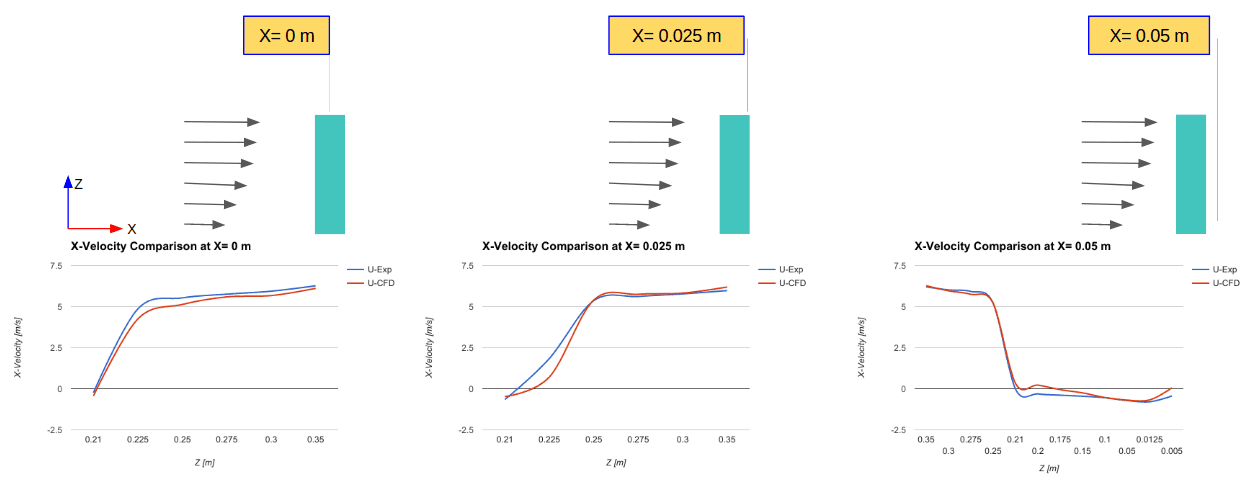
Today, the widespread availability of computing power means that full-scale simulations on complex environments can be done. SimScale exists as a prime example of this, where the availability of up to 96 computing cores and the ability to run simulations in parallel is of incredible benefit to anyone wishing to perform full-scale complex computational wind engineering simulations. The availability of such computing power in the cloud that can be accessed with a simple web browser further reduces the need to invest in costly infrastructure for fluid dynamics analysis. This benefit coupled with the available validation cases, as seen in Figure 3, for all types of environments for CWE simulations along with quick and accessible support makes the SimScale platform the ideal place for users of all skill levels to perform their simulations in.
Wind Engineering Geometry Preparation
As with all types of simulations, geometry preparation involves ensuring that the geometry to be simulated is clean, free of defects, watertight and to the correct scale. In computational wind engineering simulations, considerations of what to model are highly dependent on the end goal of the analysis. As mentioned earlier, ensuring that only the necessary geometries and details are modelled will help ensure that the computational cost is as low as possible, while reducing the workload needed to also maintain the quality of the geometry. For simulation on SimScale, it is recommended that the optimal file format is used. Regardless of format, the ability to select individual surfaces on the building or the floor is key as one wants to have absolute control over which surfaces need to be refined further in order to reduce computational cost.
Wind Engineering CWE Guidelines
The usage of computational wind engineering guidelines is key to completing accurate simulations as hassle-free as possible. However, there are a variety of guidelines that dictate different requirements and they all need to be considered carefully.
Some examples are the Architectural Institute of Japan (AIJ) guidelines for practical application [1], and the Building Construction Authority (BCA) GreenMark Technical Guide [2]. These guidelines, when followed together, should provide sufficient information regarding proper setup of CWE simulations and in effect, produce sufficiently accurate simulations.
References
- BCA, ‘BCA GreenMark Non-Residential Buildings NRB: 2015 Technical Guide and Requirements’. Building Construction Authority, 02-Nov-2016.
- Y. Tominaga et al., ‘AIJ Guidelines For Practical Applications of CFD to Pedestrian Wind Environment Around Buildings’, Journal of Wind Engineering and Industrial Aerodynamics, vol. 96, no. 10, pp. 1749–1761, Oct. 2008.