Engineering simulation or CAE is a smart way to map the actual behavior of a real-life system in a simulated environment in order to analyze the system when deployed. In the modern era, engineering simulation has evolved almost as a pre-requisite to any engineering task that needs to be done, whether it is a printed circuit board, chip design or a structural analysis of a building to be constructed. Simulation software solutions have drastically improved in the past decade and it is now possible to visualize the end product without effort. One of the most important goals of simulation is the testing and visualization of a product.
The liberty to be able to see your product before even producing a prototype is a distinct advantage. It is possible to view the product in 3D, change its appearance, choose different materials and assess their impact within different environments and much more. In some advanced simulation software solutions, one can create a scenario and put the product into it to see how it performs. Electronic simulation, mainly electronics cooling analysis, has remarkably minimized the development costs of projects. The availability of electronic components on the market and their frequency of usage play a key role when choosing electronic equipment. This capability is now available in a number of software tools when designing a PCB. Ultimately, a bill of materials can be created, which gives the actual cost of manufacturing.
A Unique Simulation Software
Diverse projects require different tools or software. There are many simulation software solutions available in the industry but SimScale is unique. Being 100% cloud-based, it allows one to seamlessly simulate, share, and collaborate in a community of more than 100,000 engineering professionals.
Its features include a comprehensive set of analysis capabilities for investigating solid mechanics, gives access to sophisticated fluid dynamics features, enables the prediction of the behavior of applications under the influence of thermal effects (thermodynamics), and supports a complete simulation workflow starting with uploading the CAD model and meshing. Finally, it also provides the liberty to either analyze the results online within the SimScale post-processing environment or download them.
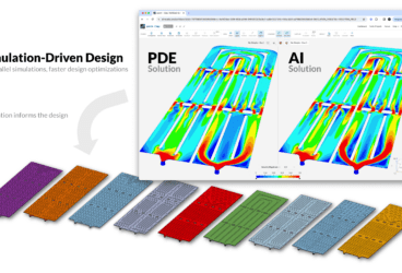
The key difference when comparing SimScale to other simulation software packages is that the whole analysis is performed in the web browser. Let’s look at a printed circuit board design simulation performed with SimScale.
Download our ‘Electronics Cooling Guide’ now for a complete overview!

Transient Thermal Analysis of a Printed Circuit Board Design (PCB)
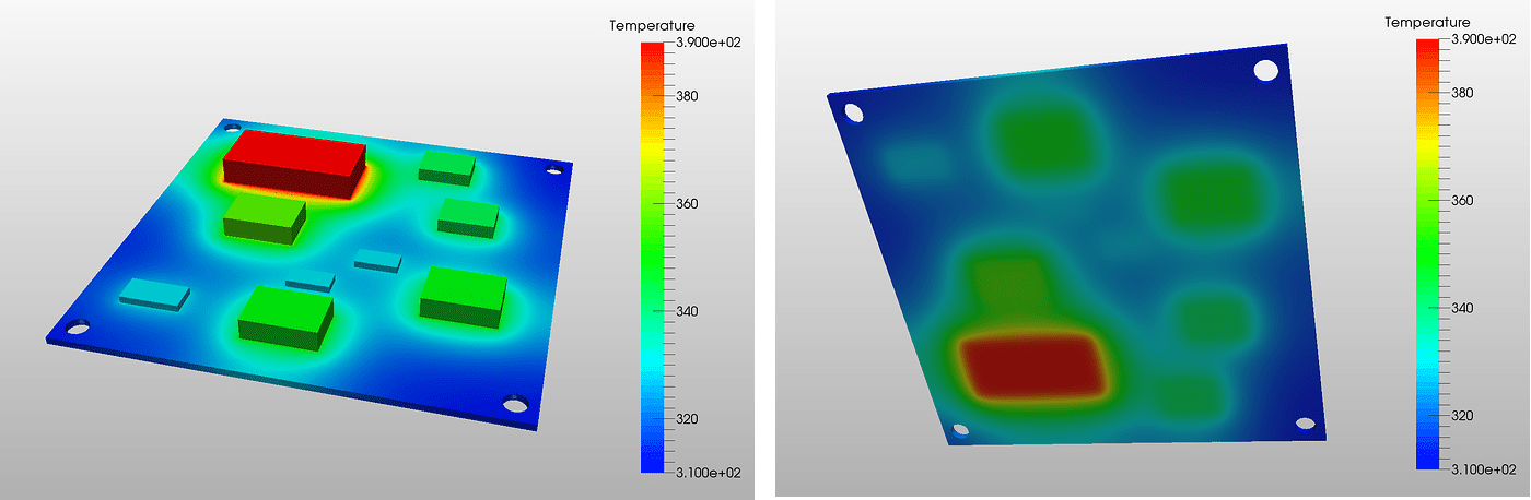
Transient heat transfer was selected as an analysis type since the temperature and surface heat flux was assumed to change over time. There were a total of nine chips on the printed circuit board, each of which was tested in slightly different environments. Five out of nine were given a temperature change over time by uploading data tables, whereas the other chips were given a surface heat flux changing over time, by also uploading data tables. In the pictures below, the top and bottom view of the PCB under analysis can be viewed. The temperature is indicated by a scale on the right of the picture. These images show the results of the temperature changing over time.
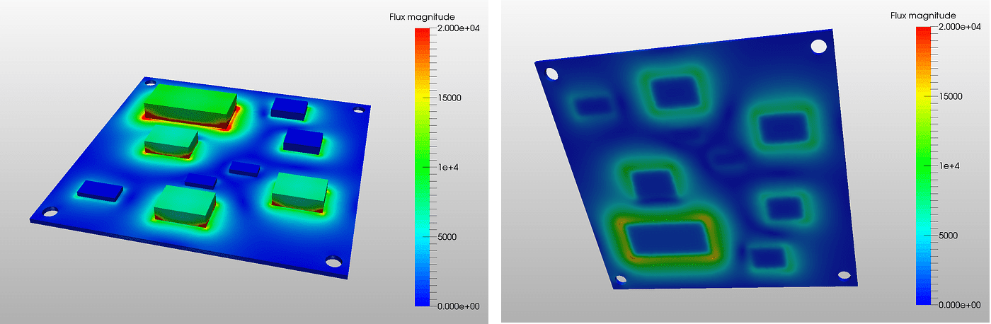
The following two images show the results of the surface heat flux changing over time.
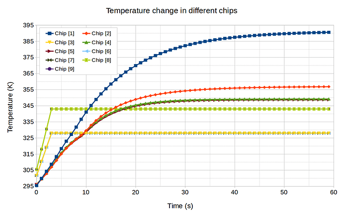
For an individual analysis of the chips, a graph was drawn. Not only does it allow the visualization of the temperature change over time, but it is also very useful for the comparison of the individual components.
The simulation was run for 300 seconds (5 minutes) and the figure below shows the animation of the final result. With this analysis, the printed circuit board design was virtually tested and analyzed in order to make the required improvements. After a simulation or a set of simulations, the CAD design can be changed according to the results and analyzed again with SimScale, until a final version is approved.
There is much more that can be done with SimScale. If you’re interested in trying it out, sign up for a free community account.
Download this free case study to learn how the thermal performance of a printed circuit board was investigated with SimScale.