Known also as “engineering equipment” or “heavy machines,” heavy equipment represents a large category of heavy-duty vehicles and big industrial machinery. Common attributes of heavy equipment are strength, oversized dimensions, working performance, and a long lifecycle because heavy equipment is an essential component of the workflow process in many powerful and demanding industries. Heavy equipment is commonly used in industries such as mining, oil and gas, energy, forestry, construction, civil engineering, military engineering, transportation and many others.
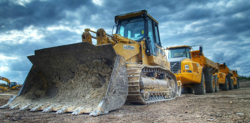
Including highly powerful machines like wheel loaders, bulldozers, graders, cranes, oversized trucks, heavy forklift or wood gathers, the heavy equipment industry has, over the last decade, been experiencing a near 6% worldwide growth rate [1]. This development is fuelled by the constantly evolving needs of humanity for natural resources, geographical spaces exploration, industrial development, transportation infrastructure, and big investments in architecture and construction.
Heavy Equipment Overview
Industries using heavy equipment are diverse and encompass many aspects of everyday life, from road construction to forestry, farming, and manufacturing to oil and mineral mining to public works and military applications.
Starting from the main applicability criteria, a wide range of heavy equipment categories can generally be classified [2]:
- Mining equipment – Horizontal drills, mining tractor, mining trucks, mining wagons
- Track-type – Tractors, bulldozers, snowcats, track skidders, agricultural tractors, and military engineering vehicles, graders, skid steer loaders
- Excavator – Dragline excavator, wheel excavator, front shovel, trencher machine, yarders, pipe layer
- Articulated – Articulated hauler, articulated truck
- Backhoe – Backhoe loader, backhoe
- Compactor – Wheel dozers soil compactors, soil stabilizer
- Highway, Railroad –Ddump truck, highway dumps, transfer train, transit-mixer, street sweeper
- Hydromatic Tools – Ballast tamper, attachments, drilling machine, pile driver, rotary tiller
- Loader – Loader, skip loader, wheel loader, track loader
- Material Handler – Aerial work and transportation platform, cherry picker, crane, forklift, trailer mount, reach stacker, telescopic handles
- Paving – Asphalt paver, cold planer, cure rig, paver, pneumatic tire compactor, road roller, slip form paver, vibratory compactor
- Scraper – Fresno scraper, scraper, wheel tractor-scraper
- Timber – Feller buncher, harvester, skidder, track harvester, wheel forwarder, wheel skidder
- Underground – Road header, tunnel boring machine, underground mining equipment
Sign up and check out our SimScale blog for much more!

Heavy Equipment — Manufacturing Challenges
Ensuring consistent high performance of heavy equipment requires a better manufacturing process, innovative design and access to the highest quality raw material. Increased competitiveness is encouraging heavy engineering processes to adopt frontier technologies and large-scale manufacturing automation.
Starting with the classic manufacturing process, which is based on common workflows that range from design and testing to production and field installation, the heavy equipment industry is facing a variety of specific difficulties related to the oversized dimensions, high quality of materials, working performance, and long-time exploitation. Let’s see how big and how heavy a few of these equipment types are, and how difficult the machine manufacturing process can be.
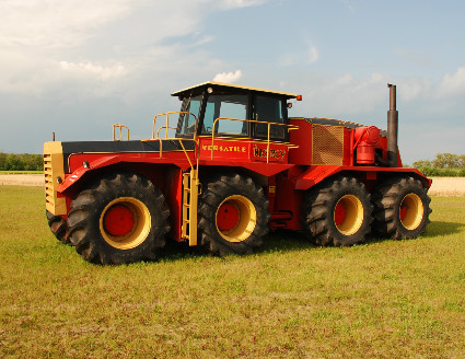
The Versatile Model 1080 „Big Roy” is one of the biggest tractors in the world [3]. It was first designed and built in 1977 by Versatile Manufacturing Ltd., located in Winnipeg-Manitoba, Canada. This massive 30-ton tractor is 30 ft (9.1m) long, 22 ft (6.7m) wide, 11 ft (3.35m) high and is powered by a 600-horsepower Cummins KTA-1150 diesel engine. The four axles carry a total of eight 30.5 X 32 tires. A modern, spacious cab is located ahead of the engine compartment, with a 550-gallon (2082l) fuel tank located at the front. Because the engine compartment is quite tall, vision to the rear of the tractor from the cab is very limited. To accommodate this, a closed-circuit TV system was installed with a dustproof, 120-degree camera pointing down at the drawbar and a 9-inch TV monitor installed in the dash.
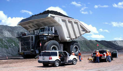
Designed in 2004 by the German manufacturer Liebherr Mining Equipment Co., the Liebherr T 282B is widely considered the largest earth-hauling truck in the world [4]. With dimensions of 14.5 m (48 ft) in length, 8.7 m (29 ft) in width, and 7.4m (24 ft) in height, the super-truck is powered by two 3,500-horsepower diesel engines coupled to a Siemens-Liebherr AC electric drive system. When fully loaded, the T 282B can achieve a top speed of 40 mph (64 km/h). Due to its exceptional size and weight, the T 282B cannot be driven on public roads. The T 282B is shipped in component form to the customer site before undergoing final assembly.
Role of Simulation in Increasing the Performance of Heavy Equipment
The previous are only two examples of engineering performances in the heavy equipment industry. Any manufacturing process for equipment this powerful should assimilate modern engineering and design solutions in order to reduce time, risk errors and financial cost. Integrated CAD/CAE solutions allow real-time corrections, dramatic reduction in the costs associated with the physical testing of prototypes and continuous improvement of product quality and performance.
Whether it’s used to virtually test heavy machines or their parts, the SimScale simulation platform has all the functionalities required to obtain the data necessary to make changes and optimizations early in the design process. Without any physical prototyping, the design engineer can make improvements and ensure the performance of heavy equipment early in the design process. Let’s see a few of the heavy equipment simulation examples that are available in SimScale’s Public Projects Library.
Structural Analysis of Heavy Equipment Components
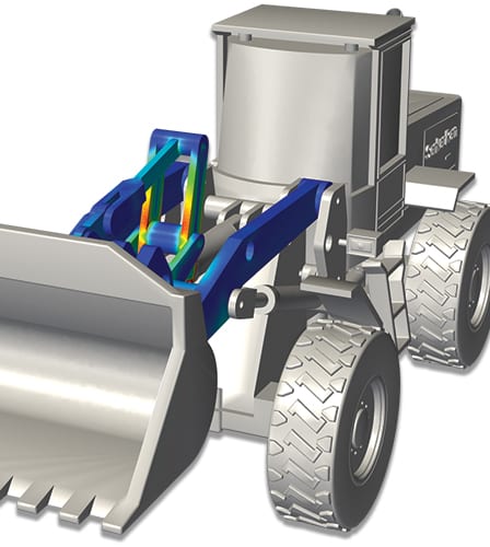
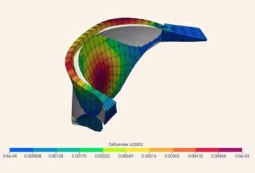
Also described in a previous SimScale blog article, the wheel loader arm project shows how a static linear structural analysis of a wheel loader arm can be carried out. The simulation results demonstrate the relative movement between the components and at the same time allow an assessment of the stress performance. Two area calculations were made to check which forces are generated by the hydraulic cylinders to lift the applied load. The figure below shows the von Mises stress response.
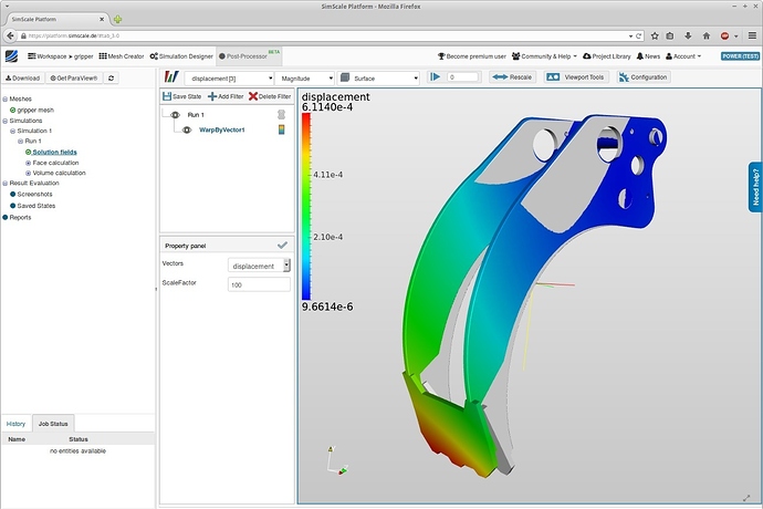
This simulation performed with SimScale is a static structural analysis of a gripper arm. The main results of the simulation show the von Mises stress performance and the displacement of the model. The most interesting aspect is the filter warp caused by the vector analysis applied to illustrate the movement of the geometry. As is shown in the image, the displacement of the gripper arm is not symmetric. This is caused by the asymmetric positioning of the hydraulic cylinder and the additional connection truss between the two gripper arms. The design engineer can now adjust the geometry to ensure a more symmetric behavior of the arm under load, which therefore improves the stress performance of the gripper arm.
Dynamic Analysis of Gears
Gears are machine elements that transmit motion by means of successively engaging teeth. According to the relative position of the axes of revolution, gears may be parallel, intersecting, and neither parallel nor intersecting [5].
In this SimScale project, a gears dynamic structural analysis, a couple of gears in contact are demonstrated. For simulation purposes, the smaller gear was completely fixed on its inner face. All degrees of freedom of the other gear were fixed, too, except the rotation around the x-axis. On the inner face of the larger gear, a moment was induced by a remote force with a torque of 20 Nm. Only a small portion of the faces—the portion that will be in contact—was subject to a frictionless augmented Lagrange contact boundary condition. After the simulation design, a dynamic structural analysis was carried out. The results allow the engineer to check the stress performance of the gears in contact early in the design process. This allows the engineer to alter the design, use another material, or check what parameters to use for a case hardening. The two pictures below visualize the von Mises stress response as well as the displacement field.

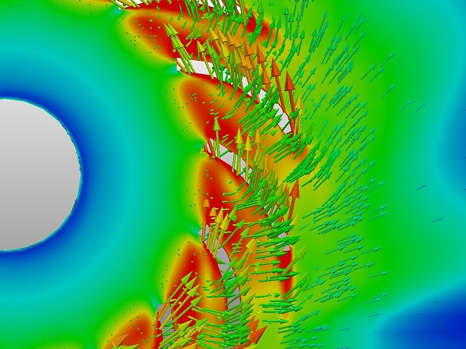
CFD Analysis of Heavy Machinery Components
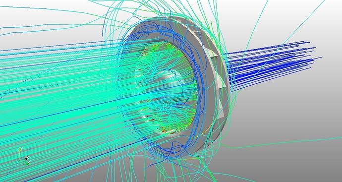
In this airflow simulation of a radial impeller, the airflow domain around the impeller has been uploaded in STEP format to the SimScale platform. This analysis includes a specific solid body for the rotating domain around the impeller. The simulation was set up using the analysis type for a steady-state, turbulent flow, utilizing a k-Omega-SST turbulence model. Additionally, the rotation of the impeller was simulated using a rotating reference zone around the impeller. The simulation results enable the early visualization of the pressure and velocity field. They also provide insight into the numerical values regarding pressure increase and volume flux.
All the projects presented in this article can be imported into your own workspace from SimScale’s Public Projects Library and used as templates.
If you haven’t signed up for SimScale yet, you can create your free account here and see for yourself how 3D engineering simulation can help you increase the performance of heavy equipment.
To discover all the simulation features provided by SimScale, download the document below.

References
- Heavyequipment.com
- Heavy_equipment, Wikipedia
- Manitoba Agriculture Museum
- Liebherr_T_282B, Wikipedia
- Zhang Y., Finger S., Behrens S. – „Introduction to Mechanisms”, Carnegie Mellon University
- Impeller definition, Wikipedia
