In architecture and construction, there are a number of technical and standard criteria that should be taken into consideration: structural behavior, seismic risks, spatial flexibility, energy efficiency, as well as thermal comfort and environmental impact.
In recent years, a broad spectrum of computer software and more specialized applications packages were created for handling complex engineering projects. Nowadays, we have dedicated applications for architecture and construction, civil engineering, industrial buildings, plants and factories, and transportation infrastructure.
With a wide range of functionalities, the SimScale simulation platform can be used to test and optimize designs in architecture and construction. This includes commercial and industrial buildings, tunnels, garages, and bridges, using a broad set of analyses, including FEA, CFD and vibration harmonic analyses.
Architecture and Construction Structural and Vibration Analysis in Architecture and Construction
In relation to structural behavior, every building engineering project is a challenge. Starting from local to general, in conventional architecture and construction processes, the structural analysis is focused on the local structural behavior of each individual element: columns, beams, floor slabs, walls, roofs, windows systems, utility pipelines, HVAC systems, etc.
Structural analysis in building optimization is based on computer packages handling a huge volume of the structure with a large number of elements. Here we can discuss stability, frequency, and stress analysis based on critical load, fundamental frequency, and maximum stress and deformations [1]:
- Basic critical loads include various couplings of basic models, concentrated top load, soils structure interaction, and complex seismic risk analysis.
- Simple and multiple stress analyses can be made for horizontal loads (wind, seismic, compression, and misalignment), loads distribution, horizontal displacements, and rotations.

Engineering masterpieces: San Francisco Golden Gate Bridge
Here are few relatively unknown facts related to the history of the Golden Gate Bridge [2]:
- The first design for the project was rejected by the public. It was considered “ugly” or “a ponderous, blunt bridge that combined a heavy tinker toy frame at each end with a short suspension span”.
- Finished in 1937, the bridge had the longest span in the world until the Verrazano Narrows Bridge was built in New York in 1964.
- It is currently the ninth-longest suspension span in the world.
A few Golden Gate Bridge facts and figures:
Total length: including approaches, 1.7 miles (8,981 feet or 2,737 m); Middle span: 4,200 feet (1,966 m).; Width: 90 feet (27 m); Clearance above the high water (average): 220 feet (67 m); Total weight when built: 894,500 tons; Total weight today: 887,000 tons (weight reduced because of new decking material); Towers: 746 feet (227 m) above the water, 500 feet (152 m) above the roadway; Steel Facts: made in New Jersey, Maryland and Pennsylvania and shipped through the Panama Canal; Total weight of steel: 83,000 tons (75,293,000 kg); Cable Facts: Two main cables pass over the tops of the main towers; each cable is made of 27,572 strands of wire. There are 80,000 miles (129,000 km) of wire in the two main cables; Cable diameter (including wrapping): 36 3/8 inches (0.92 m); Cable length: 7,260 feet (2,332 m); Traffic average crossings: about 41 million/year.
The SimScale Public Projects offer various types of analyses for bridge structures. The truss bridge is one of the most common structures analyzed in infrastructure design. A truss is a structure of connected elements forming triangular units. The connected elements (typically straight) may be stressed from tension, compression, or sometimes both in response to dynamic loads. Due to their superior strength and durability, truss bridges normally serve as river crossings for automobiles or trains. In this truss bridge eigenfrequency analysis, natural frequencies are considered. Assuming the structure may vibrate without any external load, the truss bridge is simulated for its first 20 eigenmodes. The geometry created with Onshape was uploaded to the SimScale platform. The figure below shows the displacement modal magnitude for deformation of the truss bridge at eigenmode 13. The animated version of the final model can also be found here.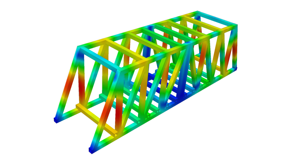
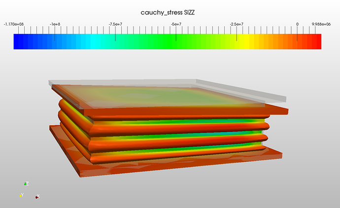
Another SimScale project is this bridge elastomer bearing pad using a nonlinear static analysis. The elastomer bearing pads are mostly used to evenly distribute the load of the bridge beams to substructures. They also sustain the compression, shear and rotational load of the bridge. The elastomer model was meshed with a second-order hexahedral mesh in order to get accurate results with minimal elements distortion. In this analysis, steel was selected as the default material for the plates and the Signorini hyperelastic model was used for the elastomer material. Three types of common elastomer pads deformation cases are simulated:
- Compression
- Compression with shear
- Combined (compression with rotation)
For all the cases, the bottom face of the lower steel plate is constrained in all directions. For compression, the top steel plate is displaced by 1 cm in the negative z-direction. Furthermore, with the same compression, the top plate is displaced by 4 cm in positive x-direction for the shear case and rotated 2 degrees along the positive y-axis for the combined deformation case. The figure below shows the results of the Cauchy stress (σz) contour plots for compression with rotation. It can be seen that the stresses are equally distributed in the elastomer due to the reinforced steel plates.
Another interesting case for special engineering projects is high-building vibration and airflow analysis. SimScale provides an interesting simulation of the Olympic Tower in Munich—one of the most iconic building structures in the Bavarian city.
Engineering masterpieces: The Olympic Tower in Munich
Located in Munich’s Olympic Park from Munich, it was built for the 1972 Summer Olympics. It has an overall height of 291 m and a weight of 52,500 tons. At a height of 190 m, there is an observation platform housing called “Rock Museum”. At 182 m, there is a revolving restaurant, which seats 230 people. A full revolution takes 53 minutes. [3]
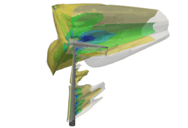
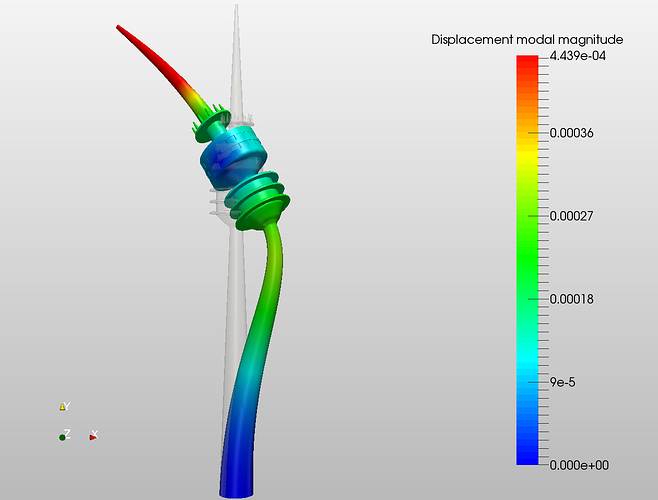
In the first Olympic Tower project, a frequency analysis has been performed with consideration for the first ten natural eigenfrequencies. The tower’s geometry, provided by Filippo Balloni, was imported to the SimScale platform. The geometry was meshed using parametrized tetrahedralization. The bottom of the tower was fixed in all directions, and the simulation was run for the first ten eigenfrequencies. The displacement modal magnitude for mode three can be seen in the figure below.
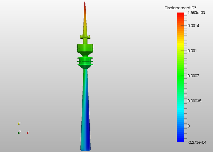
In the second project, harmonic and static analyses, subjected to a wind pressure, were performed. The displacement and von Mises stress produced in the tower due to the wind pressure (static analysis) are the main simulation results. Other results illustrate the real x, y and z (article figure) displacements from harmonic analysis, and the two graphs demonstrate the real displacement in x-direction vs. frequencies computed on the probe point of the tower top and restaurant respectively.
Architecture and Construction CFD Analysis in Building Design
HVAC simulation is very important in architecture and construction, being used for the evaluation of the building’s performance, including thermal comfort, indoor air quality mechanical system efficiency, and energy consumption. In relation to buildings, simulation is mainly used for the followings purposes:
- Thermal analysis: through the walls, roof, and floor of the buildings
- Ventilation and airflow analysis
- Orientation, site, and location selection of buildings—based on local geographical and environmental conditions.
In building design, both external and internal airflows are generally considered:
External airflow analysis in architecture and construction:
- New building positioning to minimize “canyoning” effects
- Pressure distribution on structures and wind impact on pedestrian comfort
- Using elements like walls, trees, and landscape to improve the wind flow patterns
- Design of courtyards
Closely related to building performance simulation (BPS), the internal airflow analysis is proposing to solve:
- Expected airflow rate and temperature at a given location
- Efficient design of HVAC systems
- Designing building spaces and atria for better ventilation
Engineering masterpiece: Energy Saving System from Chicago Sears Tower (Willis Tower)
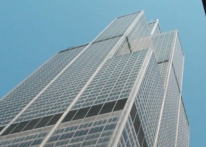
With its 527m structural height (including antennas), the Sears Tower was once the highest civilian building structure in the USA. It held this record until the completion of ONE World Trade Center, which opened in 2013, standing at a height of 546m. Besides the impressive dimensions and architectural concept, the SkyDeck is very interesting for its advanced energy saving model [4]. Each day, heat builds up inside the skin of the Willis Tower. Sunlight pours through the windows, computers and other electrical equipment generate heat, and all those warm people help push the temperature up. A sophisticated air handling system cools, filters and circulates air throughout the building. The air enters and exits each floor through carefully placed ceiling vents. Some days, heat is needed on the shady side of the building, while other times, such as cold days, perimeter heating is required in all areas of the building. At the direction of the command center, air can be filtered and exchanged between the warm and cool areas or electric boilers can supply heat throughout the offices on the perimeter. Enormous chillers are located on the main mechanical floor. These large refrigerator units cool water to chill the air and pump it to major physical plant areas throughout the building. From there, the chilled air is circulated to each floor. Four substantial cooling towers—each three stories high and located between the 106th – 109th levels—take water already used by the chillers and cool it down using fans as the water runs down the inside of each tower.
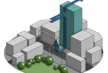
The most common analysis for buildings is airflow research for wind velocity and pressure field simulation. In this basic simulation related to airflow around a building, a CAD model of the building has been uploaded to SimScale in STEP format. The mesh was generated using the automatic hex-dominant mesh operation for external flow. In order to minimize effects of the bounding walls, a virtual wind tunnel around the building was set to 350x350x300m. The resulting mesh consists of a little more than 400,000 cells. The simulation was set up using the steady-state incompressible flow analysis type with a k-omega SST turbulence model. The airflow was simulated at 10m/s incoming wind velocity. For this simple simulation setup, the effect of the ground is neglected. In this case, the results allow the visualization of wind velocities as well as the pressure field around the building. The acting force onto the building can, therefore, be computed.
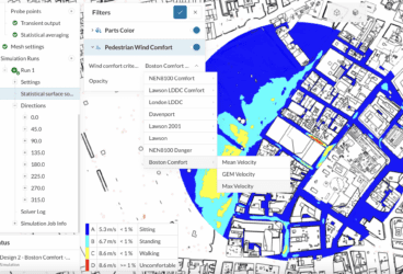
Starting from an individual building airflow analysis, it is possible to extrapolate the simulation for a building ensemble, a residential area or for a city in an architecture and construction project. In this simulation of an airflow around Singapore, a CAD model of Singapore city has been uploaded to SimScale in STEP format. The mesh was generated using the automatic hex-dominant mesh operation for external flow. The flow domain around the buildings was set to 8000x8000x1200m in order to minimize effects of the bounding walls. The resulting mesh consists of a little more than 3,000,000 cells. The steady-state incompressible flow analysis type with a k-omega SST turbulence model was set up for the simulation. The airflow was simulated at 5m/s incoming wind velocity. Like in the other case, the effect of the ground was neglected in this first simple simulation setup.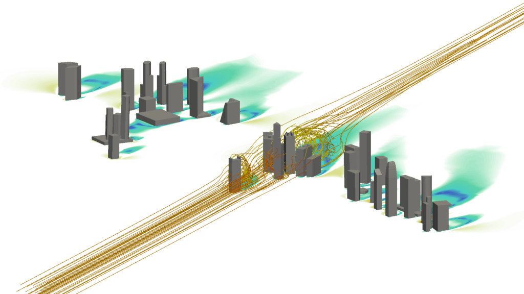
All the projects presented in this article can be imported into your own workspace and used as templates. If you want to learn more about the benefits of using engineering simulation in architecture and construction, visit our dedicated industry page.
Download this case study for free to learn how the SimScale CFD platform was used to investigate a ducting system and optimize its performance.

References
- Zalka, K. – Global Structural Analysis of Buildings, E & FN Spoon, 2000
- McCarthy E. – 20 Awesome Facts About the Golden Gate Bridge, Mintal Floss, May 2015.
- Wikipedia https://en.wikipedia.org/wiki/Olympiaturm
- Fead K. – The Hows, Whats and Wows of the Willis Tower – A Guide for Teachers, Skydeck Chicago, U.S. Equities Realty, 2009