Rising energy costs, as well as the demand on the market for efficiency, results in new challenges and requirements for room climatization. Server rooms are a very vivid example of how important climatization can be. High temperatures in server rooms can reduce the performance of the servers and drastically increase the risk of system failure. In this blog post, we want to show you how to investigate and optimize the climatization of a server room with the help of simulation.
Server Room Cooling Analysis of Server Room Cooling Process
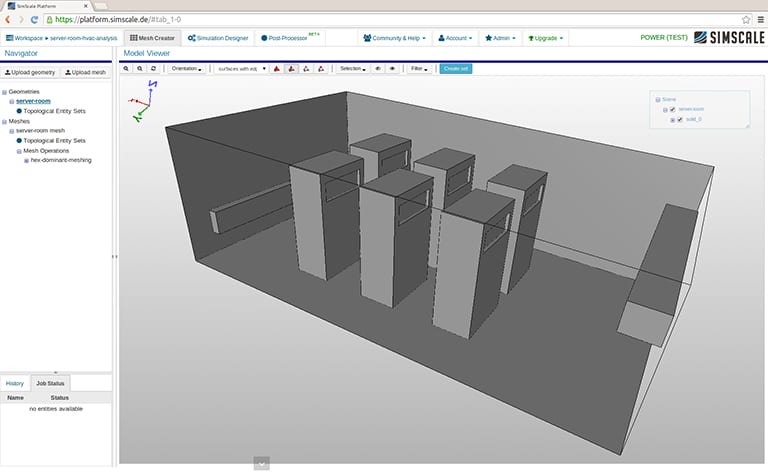
First, we upload the CAD model of the server room. The air is circulated throughout the room, entering through the inlet (lower box on the wall) and leaving it through the outlet (higher box on the wall). Hot air is streaming from the cooling outlets of the server racks into the room. The image below shows the SimScale pre-processing viewer displaying the CAD model which was uploaded as a STEP model.
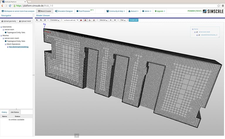
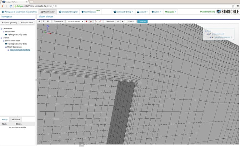
The next step is to create the computational grid. In this case, we choose an automatic hex-dominant mesh for internal aerodynamics with a boundary layer refinement. A cut view is shown in the figure below. The second figure zooms into the refined cell layers at the wall to resolve the viscous boundary layer.
The final step before we can run the simulation is to define boundary conditions and solver settings. We are using a natural convection solver and adapting the numerical settings to stabilize the simulation run. This simulation took around one hour to complete on an 8-core machine.

Server Room Cooling Conclusion
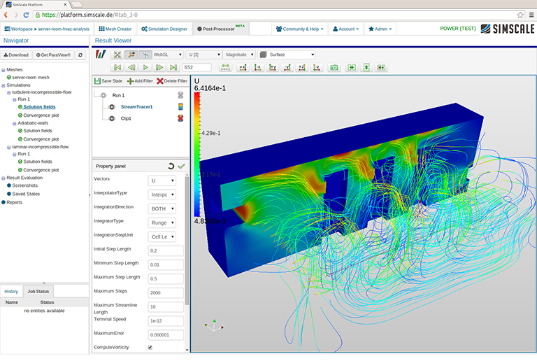
The results show that the cooling concept is working efficiently. The outgoing flow of the inlet is blocked by the server racks, and the air circulates through the gaps and in between the walls and the racks.
The hot air from the servers is carried upward by the flow and convection effects, and thereby does not increase the temperature of other servers. One can now run several “what if” scenarios to increase the efficiency of the cooling process, or to adjust the detailed layout of the servers within the room.
Do you want to learn more about HVAC simulation? Here you can find more information about how CAE can help you improve your HVAC system.
Also, this article might interest you: 5 Simulation Projects for Heating, Ventilation, and Air Conditioning.
Download this case study for free to learn how the SimScale CFD platform was used to investigate a ducting system and optimize its performance.